SUPPORT INFORMATION
M68HC11EVB/D
6-5
5
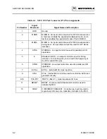
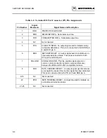
Table 6-3. Host I/O Port Connector (P3) Pin Assignments
Pin Number
Signal
Mnemonic
Signal Name and Description
1
GND
PROTECTIVE GROUND
2
RXD
RECEIVED DATA - Serial data output line.
3
TXD
TRANSMITTED DATA - Serial data input line.
4, 5
NC
Not connected.
6
DSR
DATA SET READY - An output signal used to indicate an on-
line/in-service/active status. This pin is connected to DCD pin
8.
7
SIG-GND
SIGNAL GROUND - This line provides signal ground or
common return connection (common ground reference)
between the EVB and RS-232C compatible host computer.
8
DCD
DATA CARRIER DETECT - An output signal used to indicate
an acceptable received line (carrier) signal has been detected.
This pin is connected to DSR pin 6.
9-19
NC
Not connected.
20
DTR
DATA TERMINAL READY - An input line used to indicate an
on-line/in-service/active status.
21-25
NC
Not connected.
Summary of Contents for M68HC11EVB
Page 9: ...CONTENTS x M68HC11EVB D ...
Page 35: ...MONITOR PROGRAM 3 8 M68HC11EVB D ...
Page 81: ...OPERATING INSTRUCTIONS 4 46 M68HC11EVB D ...
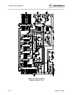
Page 97: ...SUPPORT INFORMATION 6 12 M68HC11EVB D Figure 6 3 EVB Schematic Diagram Sheet 2 of 2 ...
Page 103: ...APPLICATIONS B 2 M68HC11EVB D Figure B 1 Single Chip Mode Configuration ...

