MONITOR PROGRAM
M68HC11EVB/D
3-1
1
CHAPTER 3
MONITOR PROGRAM
3.1 INTRODUCTION
This chapter provides the overall description of the monitor program. This description will enable
the user to understand the basic structure of the program, and to modify or customize the
program for specific applications.
3.2 PROGRAM DESCRIPTION
The monitor program supplied for the EVB is called BUFFALO (Bit User Fast Friendly Aid to
Logical Operations). This program communicates via the MC6850 Asynchronous
Communications Interface Adapter (ACIA) device and the MCU Serial Communications Interface
(SCI). Refer to the buf25.asm file on the EVB diskettes for additional information pertaining to
the monitor (BUFFALO) program.
The EVB monitor program is contained in EPROM (external to the MCU). The EVB resident
MCU have the configuration (CONFIG) register ROMON bit cleared thereby disabling the MCU
internal ROM. Having the monitor program in EPROM external to the MCU at locations $E000-
$FFFF is a great advantage because it allows the user to add instructions to customize the
monitor for specific requirements.
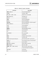
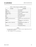
The BUFFALO monitor program consists of five parts (or sections) which are as follows:
•
Initialization
•
Command interpreter
•
I/O routines
•
Utility subroutines
•
Command table
3.2.1
Initialization
This part of BUFFALO contains all of the reset initialization code. In this section, internal RAM
locations are set up, and the I/O channel for the terminal is set up. To set up the terminal I/O port,
BUFFALO must determine if the terminal is connected to the SCI or to an external ACIA or
DUART. This is accomplished by sending a sign-on message to all ports and then waiting for the
user to type carriage return (RETURN) on whichever device is the terminal port. When
Summary of Contents for M68HC11EVB
Page 9: ...CONTENTS x M68HC11EVB D ...
Page 35: ...MONITOR PROGRAM 3 8 M68HC11EVB D ...
Page 81: ...OPERATING INSTRUCTIONS 4 46 M68HC11EVB D ...
Page 97: ...SUPPORT INFORMATION 6 12 M68HC11EVB D Figure 6 3 EVB Schematic Diagram Sheet 2 of 2 ...
Page 103: ...APPLICATIONS B 2 M68HC11EVB D Figure B 1 Single Chip Mode Configuration ...


