HARDWARE PREPARATION AND INSTALLATION
M68HC11EVB/D
2-11
11
2.4.4
Target System - EVB Interconnection
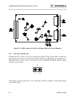
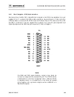
Target system to EVB interconnection is accomplished via the EVB MCU I/O port connector and
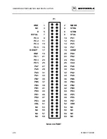
a 60 conductor flat ribbon extension cable assembly. This MCU I/O port connector P1 (shown on
the following page) is a 60-pin header that facilitates the interconnection of the cable assembly for
evaluation purposes. For connector pin assignments and signal descriptions of the EVB MCU I/O
port connector P1, refer to Chapter 6.
Two types of extension cable assembly construction techniques are available to the user. Cable
assembly construction is dependent upon the purpose or use of the EVB. The user must first
determine the primary application of the EVB in order to determine the type of cable assembly to
be constructed. Cable assembly types and construction methods are described in the following
paragraphs.
The first type of cable assembly (user supplied) is low cost and simplest to construct, and is
illustrated in Figure 2-3. This type of assembly provides an indirect connection of the EVB MCU
I/O port to the target system MCU device socket. Indirect connection is accomplished via a 60-
pin connector, installed on the target system board, that connects to the target system MCU
device socket. This connector is a double row post, 60-pin header type, Amptronics # 929715-01-
30. Target system wiring from the connector to the MCU device socket is implemented via wire
wrap or Printed Wiring Board (PWB) conductive land wiring. Uses for this type of cable assembly
are in the early development stages of the MC68HC11 MCU-based product.
The second type of cable assembly (not illustrated) is expensive and hardest to construct. This
type of assembly provides a direct connection of the EVB MCU I/O port to the target system
MCU device socket. Direct connection is accomplished via a specialized plug platform containing
a 52-lead plastic leaded chip carrier (PLCC) plug constructed by the user. This type of plug
platform mates directly with the target system MCU device socket. Uses for this type of cable
assembly are in the production stages of the developed MC68HC11 MCU-based product.
Summary of Contents for M68HC11EVB
Page 9: ...CONTENTS x M68HC11EVB D ...
Page 35: ...MONITOR PROGRAM 3 8 M68HC11EVB D ...
Page 81: ...OPERATING INSTRUCTIONS 4 46 M68HC11EVB D ...
Page 97: ...SUPPORT INFORMATION 6 12 M68HC11EVB D Figure 6 3 EVB Schematic Diagram Sheet 2 of 2 ...
Page 103: ...APPLICATIONS B 2 M68HC11EVB D Figure B 1 Single Chip Mode Configuration ...

