SUPPORT INFORMATION
M68HC11EVB/D
6-1
1
CHAPTER 6
SUPPORT INFORMATION
6.1 INTRODUCTION
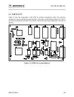
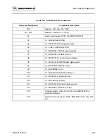
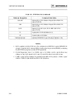
This chapter provides the connector signal descriptions, parts list with associated parts location
diagram, and schematic diagrams for the EVB.
6.2 CONNECTOR SIGNAL DESCRIPTIONS
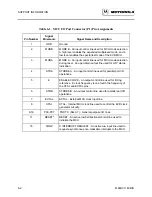
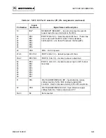
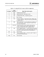
The EVB provides one input/output (I/O) connector that is used to interconnect the EVB to a
target system. Connector P1 facilitates this interconnection.
Connectors P2 and P3 are also provided to facilitate interconnection of a terminal and a host
computer, respectively. Connector P4 interconnects an external power supply to the EVB.
Pin assignments for the above connectors (P1 through P4) are identified in Tables 6-1 through 6-
4, respectively. Connector signals are identified by pin number, signal mnemonic, and signal name
and description.
Summary of Contents for M68HC11EVB
Page 9: ...CONTENTS x M68HC11EVB D ...
Page 35: ...MONITOR PROGRAM 3 8 M68HC11EVB D ...
Page 81: ...OPERATING INSTRUCTIONS 4 46 M68HC11EVB D ...
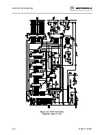
Page 97: ...SUPPORT INFORMATION 6 12 M68HC11EVB D Figure 6 3 EVB Schematic Diagram Sheet 2 of 2 ...
Page 103: ...APPLICATIONS B 2 M68HC11EVB D Figure B 1 Single Chip Mode Configuration ...

