

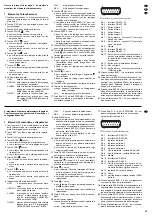

1. das Symbol für die Aufnahmeart:
bei einer manuell gestarteten Aufnahme
bei einer timergesteuerten Aufnahme
bei einer Alarmaufnahme
2. das Aufnahmesymbol
●
3. bei
eingeschalteter
Überschreibfunktion:
„OW“ (= „overwrite“)
bei
ausgeschalteter
Überschreibfunktion:
die verbleibende Speicherkapazität der Festplat-
te, z. B. „0032GB“ bei 32-GB-Restspeicherkapa-
zität
Hinweis: Bei 5-GB-Restspeicherkapazität wech-
selt die Farbe der Einblendung auf Orange und
es wird ein kurzer Warnton abgegeben. Bei
einer Restspeicherkapazität von 4 GB, 3 GB,
2 GB und 1 GB ertönt er erneut. Ist die Fest-
platte voll, stoppt die Aufnahme und in der
LED-Reihe (8) leuchtet die Anzeige HDD Full.
(Zum Ein-/Ausschalten der Überschreibfunktion
siehe Menü SYSTEM, Kapitel 9.11.)
7.1 Manuell gestartete Aufnahme
Zum Starten der Aufnahme die Taste REC (2) drü-
cken. Zum Beenden der Aufnahme die Taste STOP
(5) drücken.
Für eine manuell gestartete Aufnahme gelten die
im Menü RECORD (Kap. 9.4) eingestellten Aufnah-
meparameter.
7.2 Timergesteuerte Aufnahme
Ist die Timer-Funktion aktiviert [siehe Menü TIMER,
Kap. 9.2; bei eingeschalteter Funktion leuchtet in der
LED-Reihe (8) die Anzeige TIMER], startet und
stoppt der Recorder automatisch zu den im Menü
TIMER festgelegten Zeiten. Durch Drücken der
Taste STOP (5) kann eine Aufnahme auch vorzeitig
beendet werden.
Die Aufnahmeparameter lassen sich im Menü
TIMER für jede Aufnahme separat einstellen.
7.3 Alarmaufnahme
Ist die Funktion „externer Alarm“ aktiviert [siehe Me-
nü ALARM, Kap. 9.5; bei eingeschalteter Funktion
leuchtet in der LED-Reihe (8) die Anzeige ALARM]
und empfängt der Recorder ein Alarmsignal an
einem der vier Alarmeingänge [Pins 3, 4, 5, 6 der
Buchse EXTERNAL I/O (17)]:
1. schaltet das Gerät auf Alarmaufnahme, wenn
zum Zeitpunkt des Alarms keine Aufnahme läuft.
2. wechselt das Gerät auf Alarmaufnahme, wenn
zum Zeitpunkt des Alarms eine manuell gestartete
oder timergesteuerte Aufnahme läuft.
3. erfolgt keine Aufnahme, wenn zum Zeitpunkt des
Alarms eine Aufzeichnung abgespielt wird oder
das Einstell- oder Suchmenü aufgerufen ist.
Für die Alarmaufnahme gelten die im Menü ALARM
eingestellten Aufnahmeparameter. Der betroffene
Kamerakanal wird für die Aufnahme im Multiplex-
Modus häufiger als die übrigen Kanäle abgetastet,
so ändert sich z. B. die normale Bildfolge der Kanäle
1-2-3-4-1-2-3-4... bei einem Alarmsignal am Alarm-
eingang 1 auf 1-2-1-3-1-4-1-2-1-3-1-4...
Nach Ablauf der Alarmdauer (einstellbar unter
ALARM DURATION im Menü ALARM, Voreinstel-
lung ab Werk = 10 s) stoppt die Alarmaufnahme und
der Recorder kehrt in seinen vorherigen Betriebs-
modus zurück. Durch Drücken der Taste STOP (5)
kann eine Alarmaufnahme auch vorzeitig beendet
werden. Weitere Informationen zu den Vorgängen
bei externem Alarm sind im Kapitel 10.1 angegeben.
8 Wiedergabe
1) Zur Wiedergabe der letzten Aufzeichnung die
Taste PLAY (3) drücken. (Zur Wiedergabe einer
anderen Aufzeichnung siehe Kap. 8.4.) Die Wie-
dergabe beginnt ab dem Startpunkt der Aufzeich-
nung. Auf dem Bildschirm erscheint
und in der
LED-Reihe (8) leuchtet die Anzeige PLAY. Am
Ende der Aufzeichnung wird END eingeblendet.
2) Während der Wiedergabe lässt sich:
a mit den Zifferntasten (1) ein bestimmtes Ka-
merabild als Vollbild anzeigen
[Bei einer Aufzeichnung im Quad-Modus* wird
der jeweilige Sektor des Quad-Bilds auf Voll-
bilddarstellung vergrößert.]
b mit der Taste
(14) das Format
aufrufen
3) Wie bei der Live-Überwachung lässt sich auch im
Wiedergabebetrieb die Schärfe der Bilddarstel-
lung verändern – siehe dazu Kap. 6, Punkt 1.
4) Soll die Wiedergabe rückwärts ablaufen, wäh-
rend der Wiedergabe die Taste REW (6) drücken.
Auf dem Bildschirm erscheint
. Zum Zurück-
schalten auf Vorlauf die Taste PLAY drücken.
5) Um auf Standbild zu schalten, die Taste PAUSE
(4) drücken. Auf dem Bildschirm erscheint das
Symbol
. Zum Weiterlaufen der Wiedergabe die
Taste PLAY oder die Taste PAUSE drücken.
6) Zum Beenden des Wiedergabebetriebs die Taste
STOP (5) drücken.
●
Das gewählte Anzeigeformat für den Hauptmo-
nitor hat keinen Einfluss auf eine Aufnahme.
●
Nur Kamerakanäle, die in der Spalte REC des
Menüs CAMERA (Kap. 9.3) auf ON eingestellt
sind, werden aufgezeichnet. Ist kein Kanal auf
ON eingestellt, wird, wenn auf Aufnahme ge-
schaltet wird, „NO VIDEO COULD BE RECORD“
eingeblendet. Obwohl die Anzeige REC in der
LED-Reihe (8) leuchtet und die oben aufgeführ-
ten Aufnahmeinformationen eingeblendet wer-
den, findet in diesem Fall keine Aufnahme statt.
for timer-controlled recording
for alarm recording
2. the recording symbol
●
3. with
activated
overwrite function:
“OW” (=”overwrite”)
with
deactivated
overwrite function:
the remaining storage capacity of the hard disk,
e. g. “0032GB” for a remaining storage capacity
of 32 GB
Note: With a remaining storage capacity of 5 GB,
the colour of the insertion will change to
orange and a short warning signal will sound.
With a remaining storage capacity of 4 GB,
3 GB, 2 GB, and 1 GB it will sound again. If the
hard disk is full, the recording will stop and the
LED HDD Full in the LED row (8) will light up.
(For activating/deactivating the overwrite function
see menu SYSTEM, chapter 9.11.)
7.1 Manual recording
To start the recording, press the key REC (2). To
stop the recording, press the key STOP (5).
For a manual recording, the recording parame-
ters set in the menu RECORD (chapter 9.4) apply.
7.2 Timer-controlled recording
If the timer function is activated [see menu TIMER,
chapter 9.2; with activated function the LED TIMER
in the LED row (8) lights up], the recorder will auto-
matically start and stop at the times defined in the
menu TIMER. Press the key STOP (5) to stop a
recording at any time.
In the menu TIMER, the recording parameters
can be set separately for each recording.
7.3 Alarm recording
If the function “external alarm” is activated [see
menu ALARM, chapter 9.5; with activated function
the LED ALARM in the LED row (8) lights up] and if
the recorder receives an alarm signal at one of the
four alarm inputs [pins 3, 4, 5, 6 of the jack EXTER-
NAL I/O (17)]:
1. the unit will switch to alarm recording if no record-
ing is made at the time of the alarm.
2. the unit will switch to alarm recording if a manual
recording or a timer-controlled recording is made
at the time of the alarm.
3. no recording will be made if a recording is re-
played or the adjusting or search menu is called
at the time of the alarm.
For alarm recording, the recording parameters set in
the menu ALARM apply. For recording in the multi-
plex mode, the corresponding camera channel is
scanned more frequently than the other channels,
i.e. the normal picture sequence of the channels 1-
2-3-4-1-2-3-4... will change to 1-2-1-3-1-4-1-2-1-3-
1-4... in case of an alarm signal at alarm input 1.
At the end of the alarm time (adjustable under
ALARM DURATION in the menu ALARM, factory-
set to 10 s), the alarm recording stops and the re-
corder returns to its previous operating mode. It is
also possible to stop an alarm recording at any time
by pressing the key STOP (5). Further information
on the proceedings in case of external alarm can be
found in chapter 10.1.
8 Replay
1) To replay the last recording, press the key PLAY
(3). [To replay another recording, see chap. 8.4.]
The replay starts from the starting point of the re-
cording. The symbol
is inserted on the screen
and the LED PLAY in the LED row (8) lights up. At
the end of the recording, END is inserted.
2) During the replay it is possible
a to display a defined camera picture as a full
screen picture with the numerical keys (1)
[In case of a recording in the quad mode*, the
corresponding sector of the quad picture is
enlarged to full screen display.]
b to call the format
with the key
(14)
3) Like for live surveillance, the sharpness of the
picture display can also be modified in the replay
mode – see chapter 6, item 1.
4) For reverse replay, press the key REW (6) during
the replay.
is inserted on the screen. To return
to forward replay, press the key PLAY.
5) To switch to still picture, press the key PAUSE
(4). The symbol
is inserted on the screen. To
continue the replay, press the key PLAY or the
key PAUSE.
6) To stop the replay mode, press the key STOP (5).
●
The display format selected for the main monitor
does not affect the recording.
●
Only camera channels which are set to ON in the
column REC of the menu CAMERA (chapter 9.3)
will be recorded. If no channel is set to ON while
the unit is set to recording, “NO VIDEO COULD
BE RECORD” is inserted. Although the LED
REC in the LED row (8) lights up and the record-
ing information mentioned above is inserted, no
recording will be made in this case.
9
GB
D
A
CH
* Die Kamerabilder könnnen im Multiplex- oder im Quad-
Modus aufgenommen werden. Siehe dazu unter MODE im
Menü TIMER (Kap 9.2), bzw. unter RECORD MODE in
den Menüs RECORD und ALARM (Kap. 9.4 und 9.5).
* The camera pictures can be recorded in the multiplex
mode or in the quad mode. See MODE in the menu TIMER
(chapter 9.2) or RECORD MODE in the menus RECORD
and ALARM (chapters 9.4 and 9.5).


