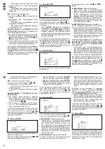

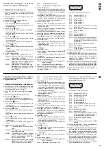

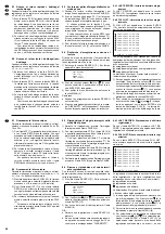


9.6 Menü DWELL
Auf dieser Menüseite können Einstellungen für den
Ausgang CALL (20) vorgenommen werden, der für
den Anschluss eines Nebenmonitors vorgesehen
ist. Der Nebenmonitor zeigt die Vollbilder der Kame-
rakanäle in Sequenzschaltung. Die Bildverweilzeit
lässt sich für jeden Kanal separat einstellen.
Bei Aufruf des Menüs ist immer der Kamerakanal 1
(CAM1) angewählt. Zum Anwählen eines anderen
Kanals mit der Taste
oder
auf die jeweilige Zei-
le springen. Mit der Taste
oder
kann der Cursor
in die Spalte NORM oder ALARM bewegt werden.
NORM (Bildverweilzeit für den Normalbetrieb)
Mit der Taste + oder - einen Wert zwischen
1 – 15 s einstellen bzw. OFF wählen, wenn der
Kamerakanal übersprungen werden soll.
ALARM (Bildverweilzeit bei externem Alarm für
mehrere Kamerakanäle)
Wird für
mehrere
Kanäle externer Alarm ausge-
löst, wird auf dem Nebenmonitor für die Dauer
des Alarms zwischen den Vollbildern der betroffe-
nen Kanäle umgeschaltet. Für die Kanäle gilt
dabei die in der Spalte ALARM eingestellte Bild-
verweilzeit: Mit der Taste + oder - einen Wert zwi-
schen 1 – 15 s einstellen bzw. OFF wählen, wenn
der Kanal übersprungen werden soll.
Wird nur für
einen
Kanal externer Alarm aus-
gelöst, zeigt der Nebenmonitor für die Dauer des
Alarms das Vollbild des betroffenen Kanals. Ist al-
lerdings in der Spalte ALARM für den Kanal die
Einstellung OFF gewählt, läuft die Sequenzschal-
tung normal weiter.
Zum
Verlassen der Menüseite
und Zurückkehren in
das Hauptmenü die Taste MENU drücken. Um wei-
tere Einstellungen vorzunehmen, mit der Taste
oder
ein anderes Untermenü anwählen oder zum
Speichern der Einstellungen
das Hauptmenü durch
Drücken der Taste MENU verlassen.
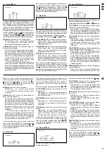
9.7 Menü PIP
Bei Aufruf dieser Menüseite schaltet das Gerät auf
das Bild-im-Bild-Format (Kap. 6.1.2) um. Für dieses
Format lassen sich die zwei Kamerakanäle und die
Position der Einblendung im Vollbild auswählen.
Die jeweilige Zeile mit der Taste
oder
anwählen.
FULL SCREEN (Wahl des Kanals für das Vollbild)
Mit der Taste + oder - den Kamerakanal aus-
wählen, der im Bild-im-Bild-Format als Vollbild
dargestellt werden soll.
PIP SCREEN (Wahl des Kanals für die Einblendung)
Mit der Taste + oder - den Kamerakanal aus-
wählen, der im Bild-im-Bild-Format als Einblen-
dung dargestellt werden soll.
POSITION (Anordnung der Einblendung im Vollbild)
Mit der Taste + oder - wählen, wo die Einblen-
dung im Vollbild platziert werden soll: D/R (unten
rechts), D/M (unten mittig), D/L (unten links), U/R
(oben rechts), U/M (oben mittig), U/L (oben links)
Zum
Verlassen der Menüseite
und Zurückkehren in
das Hauptmenü die Taste MENU drücken. Um wei-
tere Einstellungen vorzunehmen, mit der Taste
oder
ein anderes Untermenü anwählen oder zum
Speichern der Einstellungen
das Hauptmenü durch
Drücken der Taste MENU verlassen.
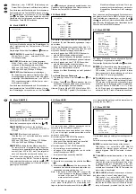
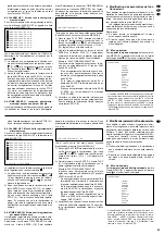
9.8 Menü DISPLAY
Auf dieser Menüseite lassen sich Einstellungen zur
Bildschirmdarstellung durchführen.
Die jeweilige Zeile mit der Taste
oder
anwählen.
TITLE DISPLAY (Ein-/Ausblendung der Kamerabe-
zeichnungen auf dem Bildschirm)
Mit der Taste + oder - die Option YES (Kamera-
bezeichnungen eingeblendet; die Bezeichnun-
gen sind im Menü CAMERA einstellbar) oder NO
(Kamerabezeichnungen ausgeblendet) wählen.
OSD COLOR (Farbauswahl für die Bildschirmein-
blendungen)
Mit der Taste + oder - die gewünschte Farbe für
die Bildschirmeinblendungen auswählen:
YELLOW (gelb), GREEN (grün), CYAN, BLUE
(blau), PINK, GRAY (grau), WHITE (weiß) oder
RED (rot).
LOSS SCREEN (Auswahl der Bildschirmdarstellung
von Kamerakanälen ohne Videosignal)
Mit der Taste + oder - die Art auswählen, in der
Kamerakanäle, für die kein Videosignal vorhan-
den ist, angezeigt werden sollen:
BLUE (blaue Fläche statt des Kamerabilds),
BLACK (schwarze Fläche statt des Kamera-
bilds), GREEN (grüne Fläche statt des Kamera-
bilds) oder RETAIN (nach einem Videosignalaus-
fall wird das zuletzt erfasste Kamerabild als
Standbild gezeigt).
TIME POSITION (Position der Datum-/Zeitangabe
auf dem Bildschirm)
Mit der Taste + oder - die Option NORMAL (Ein-
blendung von Datum/Zeit rechts oben auf dem
SUPERVISOR
[DISPLAY]
TITLE DISPLAY YES
OSD COLOR YELLOW
LOSS SCREEN BLUE
TIME POSITION NORMAL
SUPERVISOR
[PIP]
FULL SCREEN CAM1
PIP SCREEN CAM2
POSITION D/R
SUPERVISOR
[DWELL]
NORM ALARM
CAM1 02 02
CAM2 02 02
CAM3 02 02
CAM4 02 02
When the menu is called, the camera channel 1
(CAM1) is always selected. To select another chan-
nel, go to the corresponding line with the key
or
. With the key
or
, the cursor can be moved
to the column NORM or ALARM.
NORM (dwell time for the normal mode)
With the key + or -, select a value between
1 – 15 s or select OFF if the camera channel is to
be skipped.
ALARM (dwell time in case of external alarm for
several camera channels)
If an external alarm is triggered for
several
chan-
nels, the auxiliary monitor switches between the
full screen pictures of the channels concerned for
the duration of the alarm. In this case, the dwell
time adjusted in the column ALARM applies to
the channels: With the key + or -, select a value
between 1 – 15 s or select OFF if the channel is to
be skipped.
If an external alarm is triggered for a
single
channel only, the auxiliary monitor shows the full
screen picture of the channel concerned for the
duration of the alarm. However, if OFF is selected
for the channel in the column ALARM, the
sequential switching continues as usual.
To
exit the menu page
and to return to the main
menu, press the key MENU. To make further set-
tings, select another submenu with the key
or
,
or to memorize the settings, exit the main menu by
pressing the key MENU.
9.7 Menu PIP
When this menu page is called, the unit goes to the
picture-in-picture format (chapter 6.1.2). For this for-
mat, the two camera channels and the position of
the insertion in the full screen picture can be select-
ed.
Select the corresponding line with the key
or
.
FULL SCREEN (selection of the channel for the full
screen picture)
With the key + or -, select the camera channel to
be displayed as a full screen picture in the pic-
ture-in-picture format.
PIP SCREEN (selection of the channel for the inser-
tion)
With the key + or -, select the camera channel to
be displayed as an insertion in the picture-in-pic-
ture format.
POSITION (position of the insertion in the full screen
picture)
With the key + or -, select the position of the in-
sertion in the full screen picture: D/R (bottom
right), D/M (bottom centre), D/L (bottom left),
U/R (top right), U/M (top centre), U/L (top left).
To
exit the menu page
and to return to the main
menu, press the key MENU. To make further set-
tings, select another submenu with the key
or
,
or to
memorize the settings,
exit the main menu by
pressing the key MENU.
9.8 Menu DISPLAY
On this menu page, the settings for the on-screen
display can be made.
Select the corresponding line with the key
or
.
TITLE DISPLAY (insertion of the camera designa-
tions on the screen activated or deactivated)
With the key + or -, select the option YES
(camera designations inserted; the designations
are adjustable in the menu CAMERA) or NO
(camera designations not inserted).
OSD COLOR (colour selection for the insertions on
the screen)
With the key + or -, select the desired colour for
the insertions on the screen:
YELLOW, GREEN, CYAN, BLUE, PINK, GRAY,
WHITE, or RED
LOSS SCREEN (selection of the on-screen display
of camera channels without video signal)
With the key + or -, select the mode for display-
ing camera channels for which no video signal is
available:
BLUE (blue area instead of the camera picture),
BLACK (black area instead of the camera pic-
ture), GREEN (green area instead of the camera
picture), or RETAIN (after a video signal loss, the
last camera picture taken is shown as a still pic-
ture).
TIME POSITION (position of the date/time indica-
tion on the screen)
With the key + or -, select the option NORMAL
(date /time inserted on the top right of the screen)
or CENTER (date/time inserted in the centre of
the screen).
To
exit the menu
page and to return to the main
menu, press the key MENU. To make further set-
tings, select another submenu with the key
or
,
or to
memorize the settings,
exit the main menu by
pressing the key MENU.
SUPERVISOR
[DISPLAY]
TITLE DISPLAY YES
OSD COLOR YELLOW
LOSS SCREEN BLUE
TIME POSITION NORMAL
SUPERVISOR
[PIP]
FULL SCREEN CAM1
PIP SCREEN CAM2
POSITION D/R
15
GB
D
A
CH