


Das Hauptmenü hat 11 Untermenüs:
TIMER:
Einstellungen zur Timer-Funktion
CAMERA: Einstellungen für die einzelnen Kamerakanäle
RECORD: Einstellungen für manuell gestartete Aufnahmen
ALARM:
Alarmeinstellungen
DWELL:
Einstellungen für die automatische Bildweiterschal-
tung am Ausgang CALL (20)
PIP:
Einstellungen zum Bild-im-Bild-Format
DISPLAY: Einstellungen zur Bildschirmdarstellung
REMOTE: Einstellungen zur Fernsteuerung
USER:
Passwortvergabe
SYSTEM: Allgemeine Systemeinstellungen
EVENT:
Abruf der Ereignisliste
Mit den Cursor-Tasten
(4) und
(5) können die
Untermenüs angewählt und durch Drücken der
Taste ENTER (10) aufgerufen werden. Zuerst soll-
ten die Einstellungen im Untermenü SYSTEM vor-
genommen werden (siehe Kapitel 9.11).
Die in dieser Bedienungsanleitung dargestellten
Menüs zeigen die Voreinstellungen ab Werk. Zum
Zurücksetzen des Multiplexrecorders auf die Vorein-
stellungen siehe Kap. 9.11.
Auf den Menüseiten dienen:
a die Cursor-Tasten
„aufwärts“ (4) und
(5)
„abwärts“ zum Anwählen der Menüzeilen
b die Cursor-Tasten
„nach links“ (6) und
„nach rechts“ (7) zum Anwählen der Einstellfelder
in einer angewählten Menüzeile
c die (13) und - (14) zum Ändern einer
Einstellung
d die Taste ENTER (10) zum Aktivieren bestimmter
Menü-Optionen
e die Taste MENU (9) zum Verlassen einer Menü-
Seite; beim Verlassen des Hauptmenüs mit der
Taste MENU werden alle geänderten Einstellun-
gen gespeichert.
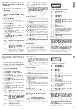
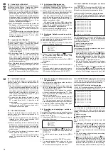
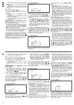
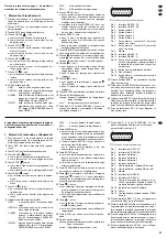
9.2 Menü TIMER
Auf dieser Menüseite werden Einstellungen für
timergesteuerte Aufnahmen (Kap. 7.2) vorgenom-
men. Bei einer timergesteuerten Aufnahme wird der
Tag, der Start- und der Endzeitpunkt der Aufnahme
festgelegt. Die Aufnahme startet und stoppt dann
automatisch zur eingestellten Zeit.
Timergesteuerte Aufnahme programmieren
Bei Aufruf des Menüs ist die erste Zeile aktiviert und
der Cursor steht in der Spalte DAY.
1) In der Spalte DAY mit der Taste + oder - den Tag
bzw. die Tage auswählen, an denen die Aufnah-
me stattfinden soll. Gewählt werden kann zwi-
schen folgenden Einstellungen:
OFF
(keine Aufnahme)
DAILY
(täglich)
MON
(montags)
TUE
(dienstags)
WED
(mittwochs)
THU
(donnerstags)
FRI
(freitags)
SAT
(samstags)
SUN
(sonntags)
MO-FR (von Montag bis Freitag)
SA-SU (Samstag und Sonntag)
SEP-30 (einstellbares Datum: Monat-Tag)
Ist diese Option angewählt, die Taste ENTER
drücken: Die Monatsangabe ist jetzt aktiviert.
Mit der Taste + oder - den gewünschten Monat
einstellen. Dann mit der Taste
die Tagesan-
gabe anwählen und mit der Taste + oder - den
gewünschten Tag einstellen. Das Datum mit
der Taste MENU bestätigen.
2) In der Spalte START den Startzeitpunkt der Auf-
nahme festlegen und in der Spalte END den End-
zeitpunkt der Aufnahme:
Mit der Taste
zuerst die Stelle für die Stun-
deneingabe anwählen und die Stunde mit der
Taste + oder - einstellen. Dann mit der Taste
die Stelle für die Minuteneingabe anwählen und
die Minuten mit der Taste + oder - einstellen.
Hinweis zum Start- und Endzeitpunkt:
Wenn als Aufnahmetag in der Spalte DAY ein
bestimmtes Datum oder ein bestimmter Wochen-
tag (MON, TUE, WED, THU, FRI, SAT oder SUN)
gewählt ist und die Aufnahme bis in den folgen-
den Tag laufen soll, muss diese in zwei Aufnah-
men aufgeteilt werden. Die Start- und End-
zeitpunkte der beiden Aufnahmen müssen dabei
jeweils im selben Tag liegen.
Beispiel: Soll eine Aufnahme immer sonntags um
11:30 Uhr starten und am jeweils darauf fol-
genden Montag um 00:20 Uhr enden, darf die
Aufnahme nicht für SUN von 11:30 bis 00:20
festgelegt werden, weil sie dann erst am
nächsten Sonntag in einer Woche um 00:20
endet. Sie muss stattdessen aufgeteilt wer-
den: die erste Aufnahme für SUN mit Start-
punkt 11:30 und Endpunkt 23:59 und die
zweite für MON von 00:00 bis 00:20.
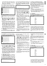
3) Mit der Taste
die Spalte IPS (images per
second = Bilder pro Sekunde) anwählen und mit
der Taste + oder - die gewünschte Aufnahme-
geschwindigkeit einstellen: 1, 2, 3, 6, 12 oder
25 Bilder/s (PAL) bzw. 1, 2, 4, 8, 15 oder 30 Bil-
der/s (NTSC). Zur Auswirkung der Aufnahmege-
schwindigkeit auf die Aufnahmezeit siehe auch
Kap. 13.2.
4) Mit der Taste
die Spalte QLT anwählen und
mit der Taste + oder - die gewünschte Aufnah-
SUPERVISOR
[TIMER]
DAY START END IPS QLT MODE
OFF 00:00 00:00 25 BASE MUX
OFF 00:00 00:00 25 BASE MUX
OFF 00:00 00:00 25 BASE MUX
OFF 00:00 00:00 25 BASE MUX
OFF 00:00 00:00 25 BASE MUX
OFF 00:00 00:00 25 BASE MUX
OFF 00:00 00:00 25 BASE MUX
TIMER ENABLE YES
The main menu has 11 submenus:
TIMER:
settings for the timer function
CAMERA: settings for the individual camera channels
RECORD: settings for manual recordings
ALARM:
alarm settings
DWELL:
settings for the automatic sequential switching at the
output CALL (20)
PIP:
settings for the picture-in-picture format
DISPLAY: settings for the on-screen display
REMOTE: settings for remote control
USER:
password assignment
SYSTEM: general system settings
EVENT:
calling the list of events
With the cursor keys
(4) and
(5) the submenus
can be selected and called by pressing the key
ENTER (10). The settings should first be made in
the submenu SYSTEM (see chapter 9.11).
The menus presented in this instruction manual
show the factory settings. For resetting the multiplex
recorder to the factory settings see chapter 9.11.
On the menu pages
a the cursor keys
“Up” (4) and
“Down” (5)
serve for selecting the menu lines.
b the cursor keys
“Left” (6) and
“Right” (7)
serve for selecting the adjusting fields in a menu
line selected.
c the keys + (13) and - (14) serve for changing a
setting.
d the key ENTER (10) serves for activating certain
menu options.
e the key MENU (9) serves for exiting a menu
page; when exiting the main menu with the key
MENU, all modified settings will be memorized.
9.2 Menu TIMER
On this menu page, settings are made for timer-con-
trolled recordings (chapter 7.2). With a timer-con-
trolled recording the day, the starting point, and the
end point of the recording are defined. The recording
will automatically start and stop at the defined time.
Programming a timer-controlled recording
When calling the menu, the first line is activated and
the cursor is in the column DAY.
1) In the column DAY, use the key + or - to select
the day or the days when the recording is to be
made. The following settings are available:
OFF
(no recording)
DAILY
MON
TUE
WED
THU
FRI
SAT
SUN
MO-FR
SA-SU
SEP-30 (adjustable date: month-day)
If this option has been selected, press the key
ENTER: The indication of the month is activat-
ed now. Select the desired month with the key
+ or -. Then select the indication of the day
with the key
and set the desired day with
the key + or -. Confirm the date with the key
MENU.
2) Define the starting time of the recording in the
column START and the end point of the recording
in the column END:
With the key
first select the place for the
input of the hour and set the hour with the key +
or -. Then select the place for the input of the
minute with the key
and set the minutes with
the key + or -.
Note concerning the starting point and the end
point:
If a certain date or a certain weekday (MON,
TUE, WED, THU, FRI, SAT, or SUN) has been
selected as a recording day in the column DAY
and the recording is to continue to the following
day, it must be divided into two recordings. For
each recording, the times of the starting point and
end point must be on the same day.
Example: If a recording is to start always on Sun-
days at 11.30 a.m. and is to stop on the follow-
ing Monday at 00:20 a.m., the recording must
not be defined for SUN from 11:30 a.m. to
00:20 a.m. as in this case it will not stop until
Sunday next week at 00:20 a.m. Instead it
must be subdivided: The first recording for
SUN with the starting point at 11:30 a.m. and
end point 23:59 and the second for MON from
00:00 a.m. to 00:20 a.m.
3) Select the column IPS (images per second) with
the key
and set the desired recording speed
with the key + or -: 1, 2, 3, 6, 12, or 25 images/s
(PAL) or 1, 2, 4, 8, 15, or 30 images/s (NTSC).
For effects of the recording speed on the record-
ing time also see chapter 13.2.
4) Select the column QLT with the key
and set
the desired recording quality with the key + or -.
The following qualities are available: BEST (best
quality), HIGH, NORM, or BASE (lowest quality).
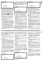
SUPERVISOR
[TIMER]
DAY START END IPS QLT MODE
OFF 00:00 00:00 25 BASE MUX
OFF 00:00 00:00 25 BASE MUX
OFF 00:00 00:00 25 BASE MUX
OFF 00:00 00:00 25 BASE MUX
OFF 00:00 00:00 25 BASE MUX
OFF 00:00 00:00 25 BASE MUX
OFF 00:00 00:00 25 BASE MUX
TIMER ENABLE YES
12
GB
D
A
CH