


5.1 Umschaltung PAL/NTSC
Das Gerät ist ab Werk auf die europäische Video-
norm PAL eingestellt, lässt sich aber auch bei Bedarf
auf die amerikanische Videonorm NTSC umstellen.
Um auf NTSC zu schalten, das Gerät von der
Stromversorgung trennen. Während die Taste FF
(7) gedrückt gehalten wird, das Gerät wieder mit
der Stromversorgung verbinden.
Um zurück auf PAL zu schalten, das Gerät von der
Stromversorgung trennen. Während die Taste
REW (6) gedrückt gehalten wird, das Gerät wie-
der mit der Stromversorgung verbinden.
5.2 Bedientasten sperren
Die Bedientasten können gesperrt werden, um zu
verhindern, dass Unbefugte das Gerät bedienen.
Da zum Aufheben der Sperrung immer ein Pass-
wort eingegeben werden muss, ist es durch Ver-
gabe von unterschiedlichen Passwörtern möglich,
die Zugriffsrechte auf die Menü-Einstellungen nur
auf eine Person bzw. mehrere Personen zu be-
schränken – zur Vergabe der Passwörter siehe
Menü USER, Kap. 9.10.
1) Zum Sperren der Bedientasten die beiden Tas-
ten MENU (9) und ENTER (10) gleichzeitig drü-
cken. Auf dem Bildschirm erscheint die Meldung
„KEY LOCKED“ und erlischt nach 10 s wieder.
2) Zum Aufheben der Sperrung die Tasten MENU
und ENTER erneut gleichzeitig drücken. Nach
dem Drücken der Tasten wird das 4-stellige
Passwort abgefragt.
a Wurden keine Passwörter vergeben, zur Bestä-
tigung des ab Werk eingestellten Passworts
„0000“ die Taste ENTER drücken. Die Sperrung
ist aufgehoben, auf dem Bildschirm erscheint
die Einblendung „KEY UNLOCKED“ für 10 s.
b Bei einer Passwortvergabe das jeweilige Pass-
wort eingeben: mit der Taste
(6) oder
(7)
nacheinander die vier Stellen des Wortes an-
wählen und mit der Taste + (13) oder - (14) die
jeweilige Zahl einstellen. Nach der Eingabe die
Taste ENTER drücken. Die Sperrung ist aufge-
hoben, auf dem Bildschirm erscheint für 10 s
die Einblendung „KEY UNLOCKED“.
Die Eingabe des „SUPERVISOR“-Passworts
berechtigt nach dem Aufheben der Tasten-
sperrung dazu, alle Seiten des Einstellmenüs
aufzurufen und die Menü-Einstellungen zu än-
dern. Bei Eingabe eines „USER“-Passworts ist
es nach dem Aufheben der Tastensperrung
zwar möglich, die Seiten des Einstellmenüs
aufzurufen (außer der Menüseite USER), es
können jedoch keine Einstellungen vorgenom-
men werden.
6 Live-Überwachung
Die Live-Überwachung der aktuellen Kamerabilder
ist über folgende Monitore möglich:
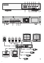
1. über den Hauptmonitor am Ausgang MAIN (19);
für diesen Monitor lassen sich verschiedene An-
zeigeformate auswählen, siehe dazu Kap. 6.1.
Um die Bildschärfe zu erhöhen, die Tasten
ENTER (10) und SEARCH (11) gleichzeitig drü-
cken (Einblendung „SHARPNESS“ für 10 s). Soll-
te die Scharfeinstellung zu einem stärkeren Bild-
rauschen führen (z. B. bei schlechter Ausleuch-
tung des Überwachungsbereichs), durch erneu-
tes gleichzeitiges Drücken der Tasten ENTER
und SEARCH zur normalen Bilddarstellung zu-
rückkehren (Einblendung „NORMAL“ für 10 s).
2. über einen Nebenmonitor am Ausgang CALL
(20); dieser zeigt alle Kamerakanäle nacheinan-
der im Vollbild-Format (Sequenzschaltung). Nicht
angeschlossene Kanäle werden übersprungen.
Im Einstellmenü (Menü DWELL, Kap. 9.6) lässt
sich die Bildverweilzeit für jeden Kanal festlegen
(Voreinstellung ab Werk 2 s).
6.1 Anzeigeformate wählen
Das für den Hauptmonitor zuletzt gewählte Anzeige-
format wird gespeichert, so dass nach der Inbetrieb-
nahme oder nach einer Stromunterbrechung wieder
die zuletzt eingestellte Bildanordnung erscheint.
6.1.1 Vollbild-Format
Soll das Bild eines Kamerakanals als Vollbild auf
dem Bildschirm dargestellt werden, die Zifferntaste
(1) des gewünschten Kamerakanals drücken.
6.1.2 Mehrfachbild-Formate
Soll nicht nur ein Kamerakanal zur Zeit auf dem
Hauptmonitor betrachtet werden, lässt sich eines
der Mehrfachbild-Formate wählen:
1. Taste
(13) für das Bild-im-Bild-Format
Auf dem Bildschirm erscheint ein Kamerakanal
im Vollbild-Format und ein weiterer Kamerakanal
als eingeblendetes kleines Bild. Im Einstellmenü
(Menü PIP, Kap. 9.7) lassen sich die gewünsch-
ten zwei Kamerakanäle und die Position der Ein-
blendung im Vollbild auswählen.
2. Taste
(12) für das Vierfachbild-Format
Am rechten Rand des Vollbilds von Kameraka-
nal 1 werden die Bilder der Kamerakanäle 2 bis 4
verkleinert eingeblendet
3. Taste
(14) für das Vierfachbild-Format
(Quad-Format):
Der Bildschirm ist zur Darstellung aller Kamera-
kanäle in vier gleich große Sektoren unterteilt.
7 Aufnahme
Der Recorder bietet drei Aufnahmearten:
1. manuell gestartete Aufnahme
2. timergesteuerte Aufnahme
3. Alarmaufnahme (durch ein externes Alarmsignal
ausgelöste Aufnahme)
Während einer Aufnahme leuchtet immer die An-
zeige REC in der LED-Reihe (8). Fällt die Stromver-
sorgung während einer Aufnahme aus, schaltet das
Gerät bei Wiederherstellung der Stromversorgung
in den vorherigen Aufnahmemodus zurück.
Auf dem Bildschirm des Hauptmonitors werden
während einer Aufnahme folgende Informationen
rechts oben eingeblendet:
3) To modify the basic settings and to programme
the unit to the individual requirements of the user,
see chapter 9.
4) To switch off, disconnect the plug of the power
supply unit from the socket.
5.1 Selection PAL/NTSC
The unit is factory-set to the European video stand-
ard PAL but it can also be set to the American video
standard NTSC, if required.
To switch to NTSC, switch off the unit and dis-
connect it from the power supply. Keep the key
FF (7) pressed while reconnecting the unit to the
power supply.
To return to PAL, switch off the unit and disconnect it
from the power supply. Keep the key REW (6)
pressed while reconnecting the unit to the power
supply.
5.2 Locking of control keys
The control keys can be locked to prevent unauthor-
ized persons from handling the unit.
As a password is always required for unlocking,
the assignment of different passwords allows to limit
the access authorization to the menu settings to a
single person or several persons only – for
assigning passwords see menu USER, chap. 9.10.
1) To lock the control keys, press both keys
MENU (9) and ENTER (10) at the same time. The
message “KEY LOCKED” is shortly inserted on
the screen and is extinguished after 10 s.
2) To unlock, press the keys MENU and ENTER
once again at the same time. After pressing the
keys, the 4-digit password is requested.
a If no passwords have been assigned, press the
key ENTER to confirm the factory-set pass-
word “0000”. The keys are unlocked and the
screen displays “KEY UNLOCKED” for 10 s.
b If a password has been assigned, enter the
corresponding password: Use the key
(6) or
(7) to select the four places of the password
one after the other, then adjust the corre-
sponding number with the key + (13) or - (14).
After the input, press the key ENTER. The
keys are unlocked and the screen displays
“KEY UNLOCKED” for 10 s.
After the keys have been unlocked, the input of
the “SUPERVISOR” password gives author-
ization to call all pages of the adjusting menu
and to modify the menu settings. After the keys
have been unlocked and a “USER” password
is entered, it is possible to call the pages of the
adjusting menu (except the menu page
USER), however, no settings can be made.
6 Live Surveillance
Live surveillance of the current camera pictures is
possible via the following monitors:
1. Via the main monitor at the output MAIN (19); it is
possible to select different display formats for this
monitor, see chapter 6.1.
To increase the sharpness of the picture,
press the keys ENTER (10) and SEARCH (11) at
the same time (“SHARPNESS” inserted for 10 s).
If the sharpness setting results in an increased
picture noise (e. g. in case of poor illumination of
the surveillance zone), return to the normal pic-
ture reproduction by pressing the keys ENTER
and SEARCH once again at the same time
(“NORMAL” inserted for 10 s).
2. Via an auxiliary monitor at the output CALL (20);
this monitor successively shows all camera chan-
nels connected in the full screen format (sequen-
tial switching). Channels which are not connect-
ed are skipped. The dwell time for each channel
can be set in the adjusting menu (menu DWELL,
chapter 9.6) [factory-set to 2 seconds].
6.1 Selecting display formats
The last display format selected for the main monitor
is memorized so that the last picture arrangement
will be displayed again after switching on the unit or
after a power interruption.
6.1.1 Full screen format
For displaying the picture of a camera channel in full
screen format on the screen, press the numerical
key (1) of the desired camera channel.
6.1.2 Multiple picture formats
For viewing more than one camera picture on the
main monitor at a time, it is possible to select one of
the multiple picture formats:
1. Key
(13) for the picture-in-picture format
The screen displays one camera channel in the
full screen format and another camera channel
as a small picture inserted. In the adjusting menu
(menu PIP, chapter 9.7), the desired two camera
channels and the position of the insertion in the
full screen picture can be selected.
2. Key
(12) for the 4-channel display format
At the right margin of the full screen picture of
camera channel 1, the pictures of camera chan-
nels 2 to 4 are inserted as size-reduced pictures.
3. Key
(14) for the quad format
For displaying all camera channels, the screen is
divided into 4 sectors of identical size.
7 Recording
The recorder offers three recording modes:
1. manual recording
2. timer-controlled recording
3. alarm recording (triggered by an external alarm
signal)
During a recording, the LED REC in the LED row (8)
always lights up. In case of power failure during a
recording, the unit will return to its previous record-
ing mode after power has been restored.
During a recording, the following information is
inserted on the top right of the screen of the main
monitor:
1. the symbol for the recording mode:
for recording started manually
8
GB
D
A
CH


