62
3 SIGNALS AND WIRING
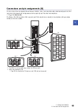
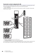
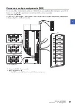
3.4 Connectors and pin assignments
3.4
Connectors and pin assignments
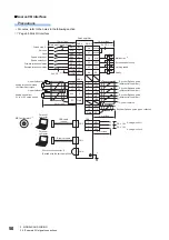
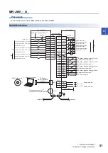
Precautions
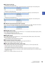
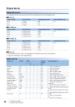
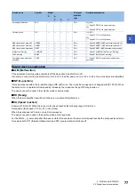
• The pin assignments of the connectors are as viewed from the cable connector wiring section.
• For information on the functional safety I/O signal connector (CN8), refer to the following page:
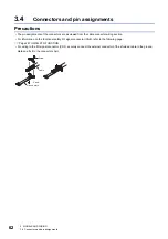
• For wiring to the I/O signal connector (CN3), securely connect the external conductor of the shielded cable to the ground
plate and fix it to the connector shell.
Screw
Cable
Screw
Ground plate
Summary of Contents for Melservo-J5 MR-J5 Series
Page 2: ......
Page 441: ...12 USING A FULLY CLOSED LOOP SYSTEM 12 7 Absolute position detection system 439 12 MEMO ...
Page 445: ......


