214
6 OPTIONS AND PERIPHERAL EQUIPMENT
6.13 Relay (recommended)
6.13
Relay (recommended)
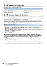
The following relays should be used with each interface.
6.14
Noise reduction techniques
Noises are classified into external noises, which enter the servo amplifier to cause it to malfunction, and those radiated by the
servo amplifier to cause peripheral equipment to malfunction. Because the servo amplifier is an electronic device that handles
small signals, the following general noise reduction techniques are required.
The servo amplifier can also be a source of noise as its outputs are chopped by high carrier frequencies. If peripheral
equipment malfunctions due to noise produced by the servo amplifier, take measures to reduce the noise. The reduction
techniques will vary slightly with the routes of noise transmission.
Noise reduction techniques
■
General reduction techniques
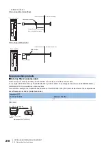
• Avoid bundling power lines (input/output lines) and signal cables together or running them in parallel to each other.
Separate the power lines from the signal cables.
• Use a shielded twisted pair cable for connection with the encoder and for control signal transmission, and connect the
external conductor of the cable to the SD terminal.
• For grounding, refer to the following.
■
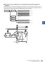
Reduction techniques for external noises that cause the servo amplifier to malfunction
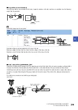
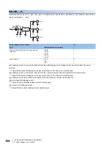
If there are noise sources (such as a magnetic contactor, an electromagnetic brake, and many relays) that make a large
amount of noise near the servo amplifier and the servo amplifier may malfunction, the following countermeasures are
required.
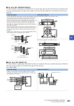
• Provide surge killers on the noise sources to suppress noise.
• Attach data line filters to the signal cables.
• Ground the shields of the encoder connecting cable and the control signal cables with cable clamp fittings.
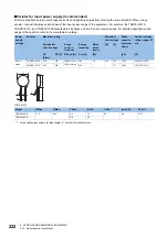
• Although a surge absorber is built into the servo amplifier, to protect the servo amplifier and other equipment against large
exogenous noise and lightning surge, attaching a varistor to the power input section of the equipment is recommended.
Interface
Selection example
Digital input signal (interface DI-1)
Relay used for digital input command signals
To prevent loose connections, use a relay for small signal (twin contacts).
(Ex.) Omron: type G2A, type MY
Digital output signal (interface DO-1)
Relay used for digital output signals
Small relay with 12 V DC or 24 V DC of rated current 40 mA or less
(Ex.) Omron: type MY
Summary of Contents for Melservo-J5 MR-J5 Series
Page 2: ......
Page 441: ...12 USING A FULLY CLOSED LOOP SYSTEM 12 7 Absolute position detection system 439 12 MEMO ...
Page 445: ......

