


8 APPLICATION INSTRUCTION
8.19 Initial State
631
8
■
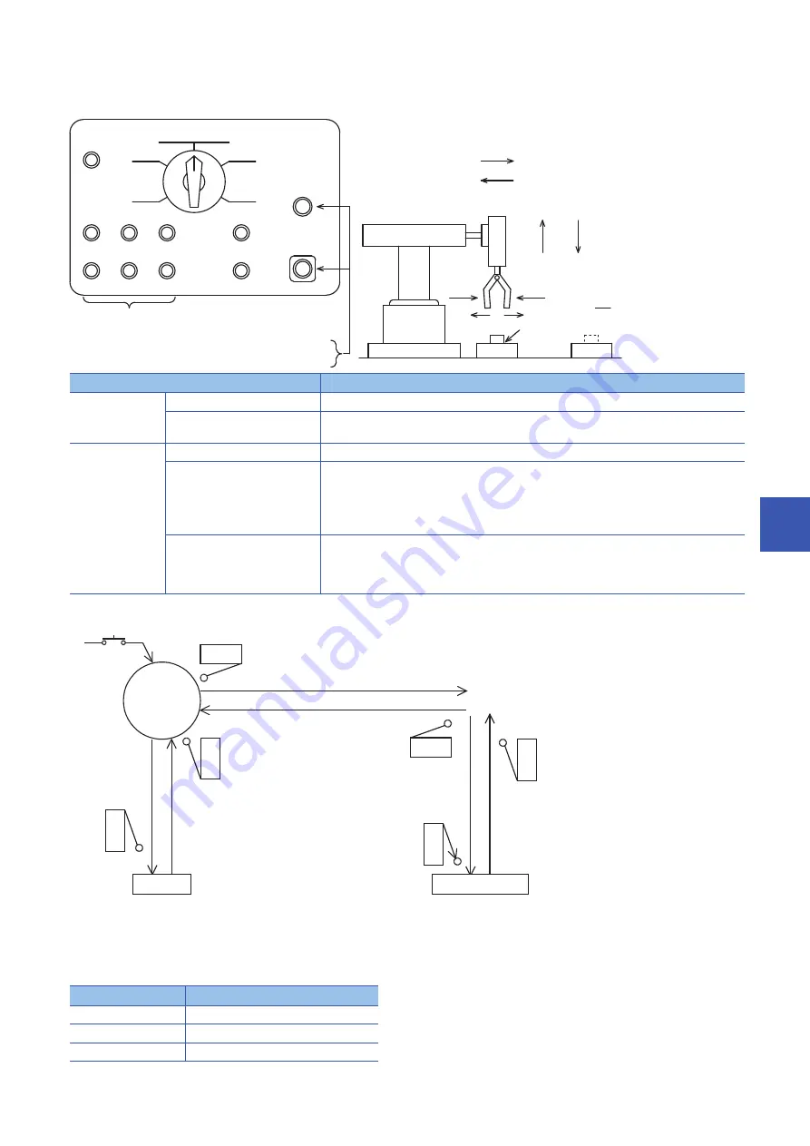
Example of IST instruction introduction (example of workpiece transfer mechanism)
• Operation mode
• Transfer mechanism
• For using IST instruction, it is necessary to assign inputs having consecutive device numbers as shown below for mode
inputs. When using non-consecutive inputs or omitting some modes, change the layout by using an auxiliary relay as the
head input for mode specification as shown in the figure below.
Operation mode
Contents of operation
Manual mode
Individual operation mode:
Each load is turned ON and OFF by an individual pushbutton switch.
Zero return operation mode:
When the pushbutton switch for zero return is pressed, the machine automatically returns to the
zero point.
Automatic mode
Stepping operation mode:
Every time the start button is pressed, the machine performs one process.
Cycle operation mode
When the start button is pressed while the machine is located at the zero point, the machine
performs one cycle of automatic operation and stops at the zero point.
If the stop button is pressed in the middle of one cycle, the machine stops immediately. When the
start button is pressed after that, the machine performs the continuous operation from the last
position, and automatically stops at the zero point.
Continuous operation mode
When the start button is pressed while the machine is located at the zero point, the machine starts
continuous operation.
When the stop button is pressed, the machine finishes the current cycle until the zero point, and
then stops at the zero point.
Input device
Assignment
X20
Individual operation mode
X21
Zero return operation mode
X22
Stepping operation mode
Unclamping Y1
Pushbutton switches for the external circuit to
turn ON and OFF the load power supply
X25
X21
X20
X22
X23
X24
Start X26
Stop X27
X5
X6
X7
X10
X11
X12
PB
PB
PB
PB
PB
PB
PB
PB
PB
PB
PB
Zero return
Zero return
operation mode
Stepping
operation
Individual
operation mode
Moving up
Leftward
travel
Unclamping
Moving down
Rightward
travel
Clamping
Continuous
operation mode
Cycle
operation mode
Power supply
Emergency stop
Pushbutton switches for individual operations
of the robot hand shown in the figure on the right
Left limit X4
Y4
Y3
Rightward Right limit X003
Leftward
Y2
Y0
Upper
limit X2
Moving down
Moving
up
Clamping Y1
Workpiece
Point A
Point B
Mechanism for transferring a workpiece from the
point A to the point B using the robot hand
Lower
limit X1
Zero point
Left limit X4
Start
X26
Upper limit X2
Clamping
Lower
limit
X1
(1) Moving
down
Y0
(3) Moving up
Y2
(2) Clamping
Y1 ON
Upper
limit
X2
Unclamping
Lower
limit
X1
(1) Moving down
Y0
(7) Moving up
Y2
(6) Unclamping
Y1 OFF
Right limit
X3
(4) Rightward Y3
(8) Leftward Y4
What is the zero point condition?
Upper limit X2 is ON, left limit
X4 is ON and unclamping Y1
is OFF.
Summary of Contents for MELSEC iQ-F FX5
Page 1: ...MELSEC iQ F FX5 Programming Manual Instructions Standard Functions Function Blocks ...
Page 2: ......
Page 17: ...15 CONTENTS ...
Page 24: ...22 MEMO ...
Page 1050: ...1048 26 TIME DATA FUNCTIONS 26 4 Division MEMO ...
Page 1068: ...1066 29 COUNTER FUNCTION BLOCKS 29 4 Counter Function Block Operation error There is no error ...
Page 1107: ...I 1105 MEMO ...
Page 1111: ......


