
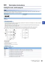


158
6 SEQUENCE INSTRUCTIONS
6.5 Master Control Instruction
Processing details
These instructions create program with efficient ladder switching by opening/closing common buses in ladders.
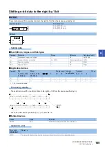
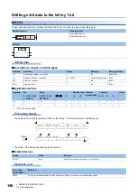
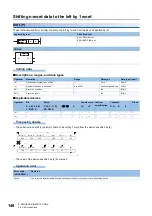
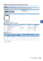
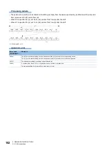
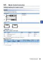
Ladder using master control is illustrated below.
(Left: Display on the engineering tool, Right: Actual operation)
■
MC
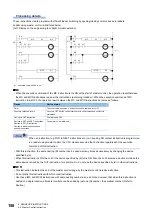
• When the execution command of the MC instruction turns ON at the start of master control, the operation result between
the MC and MCR instructions is as per the instructions (according to ladder). When the execution command of MC
instruction turns OFF, the operation result between the MC and MCR instructions becomes as follows.
When an instruction (e.g. FOR to NEXT instructions etc.) not requiring NO contact instruction is programmed
in a ladder using master control, the CPU module executes that instruction regardless of the execution
command of this instruction.
• With this instruction, the same nesting (N) number can be used as many times as necessary by changing the device
specified by (d).
• When this instruction is ON, the coil of the device specified by (d) turns ON. Also, the coil becomes a double coil when the
same device is used by the OUT instruction, for example. So, do not use the device specified by (d) in other instructions.
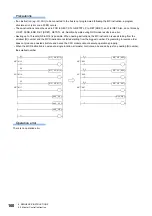
■
MCR
• This instruction indicates the end of the master control range by the master control release instruction.
• Do not prefix this instruction with NO contact instruction.
• Use these (MC and MCR) instructions with same nesting number as a pair. Note, however, that when this instruction is
nested at a single location, all master controls can be ended by just one (N) number, the smallest number. (Refer to
Caution.)
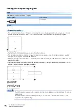
(1) Executed only when X0 is on
Device
Device status
Timer
The count value becomes 0, and both coils and contacts turn OFF.
Counters, retentive timers
Coils turn OFF but the current status of both count values and contacts is
maintained.
Devices in OUT instruction
Forcibly turned OFF.
Devices in SET and RST instructions
Devices in SFT(P) instruction
Devices in basic instructions and
applied instructions
Current status is maintained.
X0
X1
M0
N1
X3
M7
Y20
MC
M5
Y30
X6
X4
N1
MCR
X10
Y40
M0
N1
X0
X1
M0
N1
X3
M7
Y20
MC
M5
Y30
X6
X4
N1
MCR
X10
Y40
M0
N1
(1)
Summary of Contents for MELSEC iQ-F FX5
Page 1: ...MELSEC iQ F FX5 Programming Manual Instructions Standard Functions Function Blocks ...
Page 2: ......
Page 17: ...15 CONTENTS ...
Page 24: ...22 MEMO ...
Page 1050: ...1048 26 TIME DATA FUNCTIONS 26 4 Division MEMO ...
Page 1068: ...1066 29 COUNTER FUNCTION BLOCKS 29 4 Counter Function Block Operation error There is no error ...
Page 1107: ...I 1105 MEMO ...
Page 1111: ......


