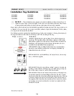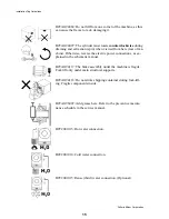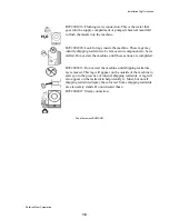
Ê
Setting Procedures
In order to protect against lateral “creeping” of the machine during operation, due to vibration, it is recom-
mended to roughen the area of the floor where grout will be applied. Anchor bolts are not required; they are how-
ever, recommended on tilting machines. Anchor bolt locations are shown on the dimensional drawing for each
machine. With the machine near the final destination, unbolt the shipping skids. Observing all precautions, lift the
machine off its skids and lower the machine onto blocks as follows.
Ë
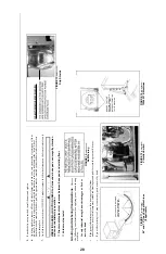
For 42", 48" and 64" Open Pocket Machines
1. Place blocks in each of the four corners of the foundation. The blocks should be high enough to hold the base
plate approximately 1" above top of slab (See FIGURE 3).
2. Lower the machine onto blocks and shim the machine as required until it is level. When leveling the machine,
place the level on the top edge of the frame, not on the belt guard.
3. When the machine is level and has room
for at least 1" of grout under each base
plate, apply the grout under the full
length of each base plate. Take care to
fill all voids with grout to assure that
there is a solid base of grout under each
base plate (for additional information,
see “Grouting and Anchoring Considera-
tions” in this section).
4. When the grout has hardened, tighten
down the anchor bolts (if used) evenly
using only one quarter turn on each bolt
before moving to the next one. While
tightening, frequently skip from front to
back and right to left to insure uniform
tension. After tightening all bolts, check
each bolt at least twice during the first
week of operation. At this point, service
connections (air and electric power)
should be made to the machine. See
“HYDRO-CUSHION
®
SERVICE CON-
NECTIONS...” for procedures.
5. With air and power connected, set the Master Switch to FORMULA or to ON (as appropriate) to activate the
push-downs, then remove hold down bolts and plates (marked with red) which hold the shell to the frame.
De-energize machine.
6. On 42" and 48" tilting machines only, remove the four hold down bolts (marked with red) that hold the lower
side frame channels to the base pad. On 64" tilt forward only machines (BTL models), remove the rear tilt
wheel clamps only. On 64" tilt both way machines (BTN models), remove all four tilt wheel clamps.
Clamps to be removed will be marked with red.
Î
FIGURE 3
(MSIN0203AE)
Î
Setting 42", 48", or 64" Open Pocket Machines
REMOVE SHIPPING RESTRAINTS BEFORE
ATTEMPTING TO RUN MACHINE but only
after machine is in place. Restraints are usually
marked with red, and may be concealed behind
access panels.
REPLACE THOSE FEATURES WHICH ARE
PART OF MACHINE STRUCTURE.
Î
FIGURE 4
(MSIN0203AE)
Î
Shipping Restraints
A SUSPENSION TYPE MACHINE
CAN "WALK" OUT OF POSITION
DURING EXTRACT, ENDANGER-
ING PERSONNEL AND DAMAG-
ING EQUIPMENT, IF NOT
PROPERLY INSTALLED.
Roughen floor, install anchor bolts and
grout under all base pads to prevent
"teeter-totter" and sideways movement.
REMOVE ALL SHIPPING RESTRAINTS but only after
machine is in place.
THE MACHINE WILL MALFUNCTION AND MAY BE DAMAGED
UNLESS ALL SHIPPING RESTRAINTS (USUALLY MARKED
WITH RED) ARE REMOVED. Restraints may be located behind
access covers. These include but are not limited to:
Cylinder hold-down bolts, brackets, straps and/or blocking
(suspension type machines).
Vibration safety switch restraint (all 36" and larger machines).
REPLACE FASTENERS WHICH ARE PART OF MACHINE
STRUCTURE.
TO REMOVE BRAKE BAND SHIPPING BLOCK
once machine is connected to electricity and air.
1. Energize machine.
2. Turn brake on using manual operating procedures (see
manual).
3. Insure that no one can inadvertently operate the machine
controls; then using tools, not bare hands, remove block while
brake is released.
4. Manually turn brake off.
Î
FIGURE 5
(MSIN0203AE)
Î
Anchor and Grout Warning
25
Summary of Contents for 42044SR2
Page 2: ......
Page 4: ......
Page 8: ......
Page 9: ...Installation 1 5 ...
Page 37: ...Î FIGURE 8 MSIN0301AE Î Vibration Switch Î FIGURE 9 MSIN0301AE Î 60 Staph Guard 33 ...
Page 51: ...586DA4 BUecU CicdU CSXU QdYS B5EC5 D1 9 CD1 1D9 1 4 5B1D9 C9 1 15 1F _V 47 ...
Page 53: ...Dimensional Drawings 2 49 ...
Page 54: ......
Page 55: ...51 ...
Page 56: ...52 ...
Page 57: ...53 ...
Page 58: ...54 ...
Page 59: ...55 ...
Page 60: ...56 ...
Page 61: ...57 ...
Page 62: ...58 ...
Page 63: ...59 ...
Page 64: ......
Page 65: ...61 ...
Page 66: ...62 ...
Page 67: ...63 ...
Page 68: ...64 ...


