Pellerin Milnor Corporation
Installation Tag Guidelines
BNWG4I01.R01 0000187278 A.2 5/22/18 4:30 PM Released
42044SR2
42044SR3
42044WR2
42044WR3
60044SR2
60044SR3
60044WR2
60044WR3
72044SR2
72044SR3
72044WR2
72044WR3
NOTICE:
This information may apply to models in addition to those listed above. It
applies to paper tags. It does not apply to the vinyl or metal safety placards, which must
remain permanently affixed to the machine and replaced if no longer readable.
Paper tags on the machine provide installation guidelines and precautions. The tags can be tie-on
or adhesive. You can remove tie-on tags and white, adhesive tags after installation. Yellow adhe-
sive tags must remain on the machine.
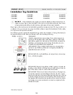
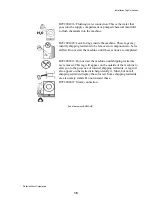
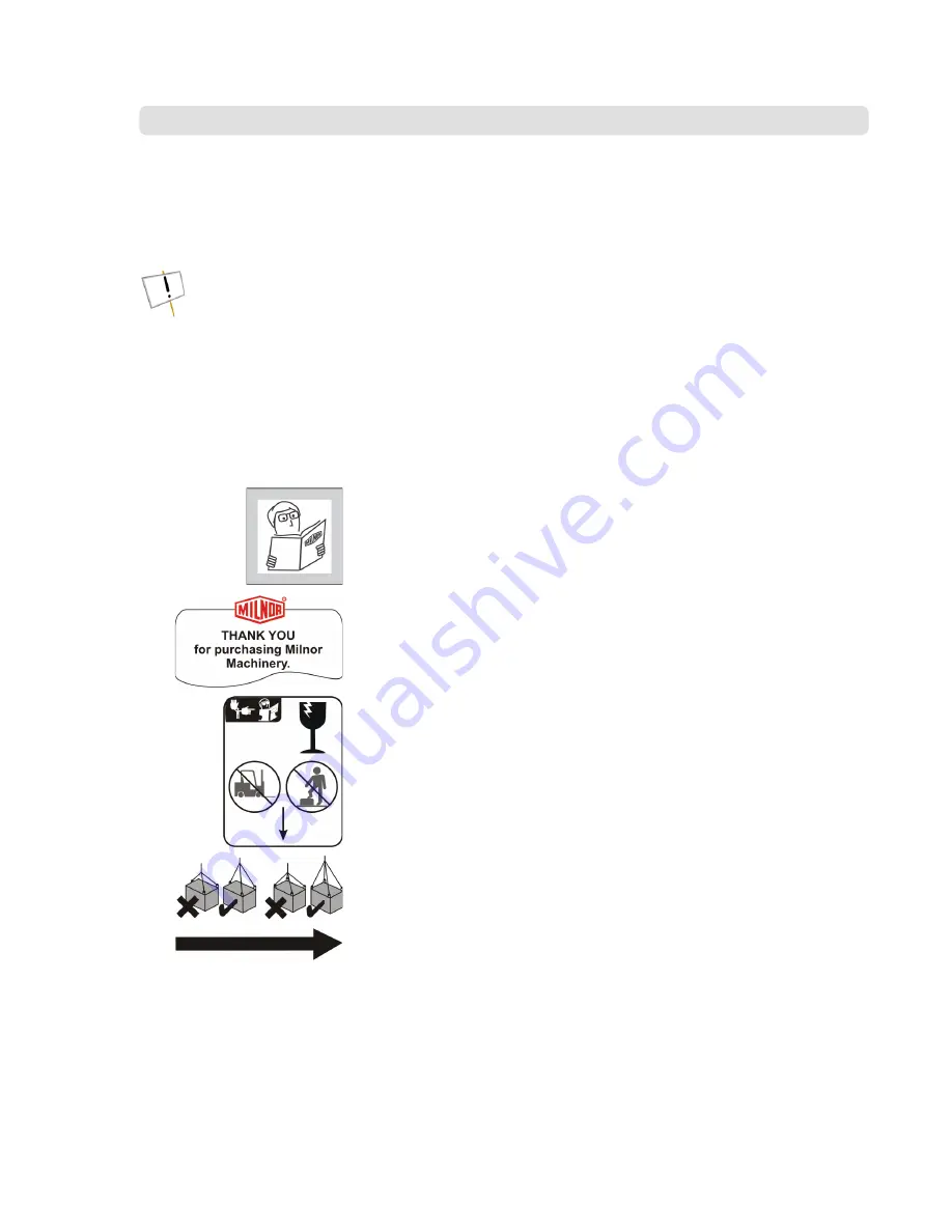
The following entries explain the installation tags. Each entry includes: 1) the tag illustration, 2)
the tag part number at the bottom of the tag, and 3) the meaning of the tag.
Display or Action
Explanation
Read the manuals before proceeding. This symbol appears on
most tags. The machine ships with safety, operator, and routine
maintenance guides for customer use. Milnor dealer manuals for
installing, commissioning, and servicing the machine are also
available from the Milnor Parts department.
B2TAG88005: This carefully built product was tested and in-
spected to meet Milnor performance and quality standards by
(identification mark of tester).
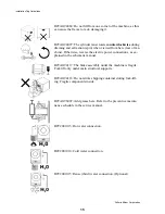
B2TAG94078: Do not forklift here; do not jack here; do not step
here—whichever applies.
B2TAG94079: Rig for crane lifting (either 3-point or 4-point, de-
pending on the number of lifting eyes provided) using a steep an-
gle on the chains (closer to vertical than horizontal).
B2TAG94081: Motor must rotate in this direction. On single mo-
tor washer-extractors and centrifugal extractors, the drive motor
must turn in this direction during draining and extraction. This tag
is usually wrapped around a motor housing. If the motor turns in
the opposite direction when the machine is first tested, the electri-
cal hookup is incorrect and must be reversed as explained in the
schematic manual.
I
BNWG4I01 / 2018213
BNWG4I01
0000187279
A.2
5/22/18 4:30 PM
Released
14
Summary of Contents for 42044SR2
Page 2: ......
Page 4: ......
Page 8: ......
Page 9: ...Installation 1 5 ...
Page 37: ...Î FIGURE 8 MSIN0301AE Î Vibration Switch Î FIGURE 9 MSIN0301AE Î 60 Staph Guard 33 ...
Page 51: ...586DA4 BUecU CicdU CSXU QdYS B5EC5 D1 9 CD1 1D9 1 4 5B1D9 C9 1 15 1F _V 47 ...
Page 53: ...Dimensional Drawings 2 49 ...
Page 54: ......
Page 55: ...51 ...
Page 56: ...52 ...
Page 57: ...53 ...
Page 58: ...54 ...
Page 59: ...55 ...
Page 60: ...56 ...
Page 61: ...57 ...
Page 62: ...58 ...
Page 63: ...59 ...
Page 64: ......
Page 65: ...61 ...
Page 66: ...62 ...
Page 67: ...63 ...
Page 68: ...64 ...


