Ë
52", 60" and 72" Open Pocket Machines
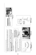
1. Lower the machine onto removable blocking, such that the shell front and shell back are resting on the block-
ing as shown in FIGURES 6 and 9 (For 52" and 60" machines, place blocking with one in the front and two
in the rear. For 72" machines, place two in the front and one in the rear). The blocking must provide for 1"
minimum clearance between the floor and the base pads.
2. Place a level on the frame front, upper right and left cross brace, and lower rear cross brace. 52" and 60"
machines must be level at each of these locations. 72" machines sit at a 1
o
angle sloping down to the back.
To approximate this angle when leveling on the side cross braces, use a 28" bubble level with 3/4" shim at
the rear.
3. When the machine is level and has room for at least one inch of grout under each base pad, apply the grout
under the full length of each base pad. Take care to fill all voids with grout to assure that there is a solid
base of grout under each base pad (for additional information, see “Grouting and Anchoring Considera-
tions” in this section).
4. When the grout has hardened, remove the shell hold-down bolts. The shell will be lifted by the HYDRO-
CUSHION
®
springs so that the temporary blocking may be removed.
Î
FIGURE 6
(MSIN0203AE)
Î
Setting 52" and 60" Open Pocket Machines
Î
FIGURE 7
(MSIN0203AE)
Î
Tilting Precautions
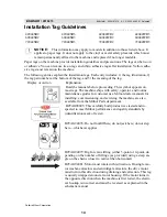
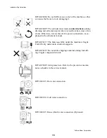
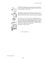
WARNING
1. MACHINE MUST BE LEVEL AND GROUTED BEFORE THE
SHIPPING LOCKDOWN CLAMPS FOR THE TILT BASE ARE
REMOVED. THIS IS NECESSARY BECAUSE IF YOU REMOVE
THEM BEFORE THE MACHINE IS LEVEL AND GROUTED
THEN IT IS POSSIBLE TO HAVE ONE LEG NOT PROPERLY
LEVELED.
2. REMOVE SHIPPING TILT WHEEL LOCKDOWN CLAMPS
BEFORE ATTEMPTING TO TILT MACHINE.
3. TILT BOTH WAY - REMOVE ALL FOUR.
TILT FORWARD ONLY - REMOVE REAR TWO.
Î
FIGURE 8
(MSIN0203AE)
Î
Tilt Wheel Clamps (BTN and BTL models only)
Î
FIGURE 9
(MSIN0203AE)
Î
Setting 72" Open Pocket Machines
26
Summary of Contents for 42044SR2
Page 2: ......
Page 4: ......
Page 8: ......
Page 9: ...Installation 1 5 ...
Page 37: ...Î FIGURE 8 MSIN0301AE Î Vibration Switch Î FIGURE 9 MSIN0301AE Î 60 Staph Guard 33 ...
Page 51: ...586DA4 BUecU CicdU CSXU QdYS B5EC5 D1 9 CD1 1D9 1 4 5B1D9 C9 1 15 1F _V 47 ...
Page 53: ...Dimensional Drawings 2 49 ...
Page 54: ......
Page 55: ...51 ...
Page 56: ...52 ...
Page 57: ...53 ...
Page 58: ...54 ...
Page 59: ...55 ...
Page 60: ...56 ...
Page 61: ...57 ...
Page 62: ...58 ...
Page 63: ...59 ...
Page 64: ......
Page 65: ...61 ...
Page 66: ...62 ...
Page 67: ...63 ...
Page 68: ...64 ...


