


Technical Information
89
DGC 6xxx
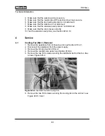
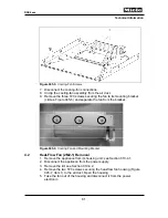
Figure 045-19:
Screws Securing Distributors, Position Switch Mounting Bracket and
Air Duct
Note:
There are two additional screws across the front that could not be shown in
Figure 045-19.
4.11
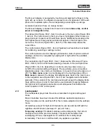
Roast Probe Electronic (N1-6) Removal
1. Remove the appliance from its housing unit; see Section 010-4.1.
2. Disconnect the appliance from the power supply.
3. Remove the lid; see Section 010-4.2.
4. Disconnect the roast probe antenna connection.
5. Disconnect the roast probe electronic (Figure 045-20, Item 1) and release
it from the electronics mounting bracket.
1
2
Summary of Contents for DGC 6 Series
Page 1: ...TECHNICAL INFORMATION DGC 6xxx Combi Steam Ovens 2018 Miele USA ...
Page 15: ...Technical Information 15 DGC 6xxx 010 Casing ...
Page 23: ...Technical Information 23 DGC 6xxx 020 Door ...
Page 27: ...Technical Information 27 DGC 6xxx 030 Cavity ...
Page 43: ...Technical Information 43 DGC 6xxx 035 Steam Generator Convection Fan ...
Page 57: ...Technical Information 57 DGC 6xxx Figure 035 14 Terminal Block ...
Page 58: ...Technical Information 58 DGC 6xxx 040 Water Container Drive ...
Page 68: ...Technical Information 68 DGC 6xxx 045 Air Duct Power Electronic ...


