Technical Information
7
DGC 6xxx
Figure 030-9: Service Panel Screws ............................................................................... 35
Figure 030-10: Lighting Assembly Nuts .......................................................................... 36
Figure 030-11: Convection Heater Temperature Limiter ................................................. 37
Figure 030-12: Bottom Heat Temperature Limiter .......................................................... 38
Figure 030-13: Cooling-Air Temperature Sensor, Heat-Flow Fan Housing and Hose .... 38
Figure 030-14: Heat-Flow Fan Housing Screws ............................................................. 39
Figure 030-15: Heat-Flow Temperature Sensor Housing ............................................... 40
Figure 030-16: Heat-Flow Temperature Sensor Installation ........................................... 41
Figure 030-17: Temperature Sensor and Seal ................................................................ 41
Figure 030-18: Roast Probe Socket ................................................................................ 42
Figure 035-1: Pinch/Drain Valve ..................................................................................... 45
Figure 035-2: Drain Pump ............................................................................................... 46
Figure 035-3: Old Hose Positioning ................................................................................ 50
Figure 035-4: New Hose Positioning ............................................................................... 50
Figure 035-5: Air Flap Motor ........................................................................................... 51
Figure 035-6: Cavity Temperature Sensor Screws ......................................................... 52
Figure 035-7: Drain Pump Removal ................................................................................ 52
Figure 035-8: Steam Generator/Mounting Bracket Assembly (Right Side Shown) ......... 53
Figure 035-9: Steam Generator/Mounting Bracket Assembly, Upside Down ................. 54
Figure 035-10: Installing the Steam Generator at at Slight Angle ................................... 54
Figure 035-11: Inner Rear Panel Screws ........................................................................ 55
Figure 035-12: Convection Fan Screws .......................................................................... 55
Figure 035-13: Drain Valve Removal .............................................................................. 56
Figure 035-14: Terminal Block ........................................................................................ 57
Figure 040-1: Leaf Springs on Telescopic Rails ............................................................. 64
Figure 040-2: Lift Motor Screws ...................................................................................... 65
Figure 040-3: Cog Wheel Setting .................................................................................... 66
Figure 040-4: Water Container Removal ........................................................................ 66
Figure 040-5: Water Container Spring ............................................................................ 67
Figure 045-1: Wireless Roast Probe System .................................................................. 74
Figure 045-2: Wireless Roast Probe ............................................................................... 74
Figure 045-3: Inserting the Wireless Roast Probe .......................................................... 76
Figure 045-4: Distributor behind Cooling Fan ................................................................. 80
Figure 045-5: Cooling-Fan Screws ................................................................................. 81
Figure 045-6: Cooling Fan and Mounting Bracket .......................................................... 81
Figure 045-7: Heat-Flow Fan Housing Screws ............................................................... 82
Figure 045-8: Heat-Flow Fan Orientation (Top View) ..................................................... 82
Figure 045-9: Feed Pump ............................................................................................... 83
Figure 045-10: Position Switch Screws ........................................................................... 83
Figure 045-11: Water Container Switches ...................................................................... 84
Figure 045-12: Lighting Electronic .................................................................................. 84
Figure 045-13: Bracket in Front of Lighting Electronic .................................................... 85
Figure 045-14: Power Electronic ..................................................................................... 85
Figure 045-15: Inlet Valves ............................................................................................. 86
Figure 045-16: Inlet Valve Mounting Bracket .................................................................. 87
Figure 045-17: Cooling-Fan Temperature Limiter ........................................................... 87
Figure 045-18: Electronics Bracket Screws .................................................................... 88
Summary of Contents for DGC 6 Series
Page 1: ...TECHNICAL INFORMATION DGC 6xxx Combi Steam Ovens 2018 Miele USA ...
Page 15: ...Technical Information 15 DGC 6xxx 010 Casing ...
Page 23: ...Technical Information 23 DGC 6xxx 020 Door ...
Page 27: ...Technical Information 27 DGC 6xxx 030 Cavity ...
Page 43: ...Technical Information 43 DGC 6xxx 035 Steam Generator Convection Fan ...
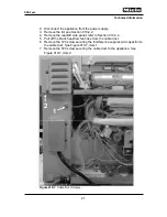
Page 57: ...Technical Information 57 DGC 6xxx Figure 035 14 Terminal Block ...
Page 58: ...Technical Information 58 DGC 6xxx 040 Water Container Drive ...
Page 68: ...Technical Information 68 DGC 6xxx 045 Air Duct Power Electronic ...


