U
U
s
s
e
e
r
r
M
M
a
a
n
n
u
u
a
a
l
l
Revision 8.6
SECTION 2 : SYSTEM DESIGN
27
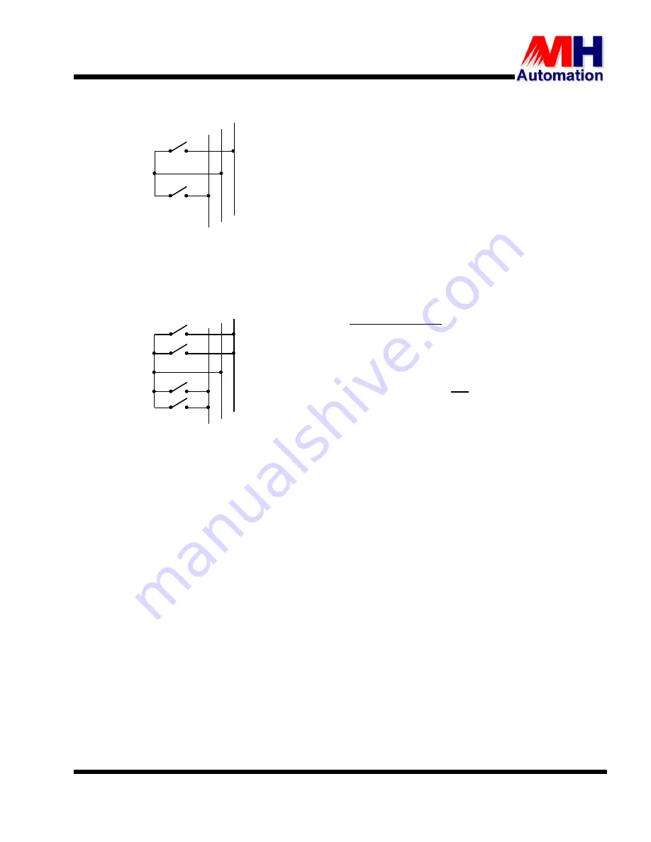
2.15.3.
V Connections
Contactor
Ith
= Motor Rotor Current
Example: Motor Rotor Current =
100 A
Contactor selected ≥
100 A Ith
2.15.4.
W Connections
Contactor
Ith
= Motor Rotor current
1.6
Example: Motor Rotor Current =
100 A
Contactor selected ≥
100
1.6
=
62.5 A Ith
2.16. MOTOR THERMAL PROTECTION UNIT -
This feature is not yet implemented
The THYROMAT has built in motor thermal protection for Class 5 and Class 10 applications the thermal
protection required can be selected from the keypad.
It is normally accepted to protect slip-ring motors with a Class 5 I
2
t temperature curve. In severe duty
applications where high ambient temperatures exist or the motor is exposed to heat radiation, it is
recommended that a Class 5 temperature curve is used and the motor power (kW) is rated accordingly so
as to ensure a reliable installation.
This method of protection does not monitor the thermal state of the motor accurately, because it can only
monitor the current drawn by the motor but does not take in consideration ambient and other essential
conditions which may affect the temperature rise of the motor. Therefore it is recommended that
wherever possible, PTC thermistor probes and associated relays be used. This will offer additional
protection against influencing factors such as, overheating due to a faulty motor ventilation fan, abnormal
rise in ambient temperature, abnormal friction in the system due to mechanical or brake failure and
unexpected severe duty operations.
In the case of a multi-motor system it is recommended that each motor must have its own external motor
protection unit (MPU) to enable the individual monitoring of each motor. In this event, the size of the
selected MPU should accurately cover the motor’s rated current range and must be set according to this
current range or to the mechanical power equivalent current rating, which should effectively be lower than
that of the rated motor current.


