U
U
s
s
e
e
r
r
M
M
a
a
n
n
u
u
a
a
l
l
Revision 8.6
SECTION 2 : SYSTEM DESIGN
14
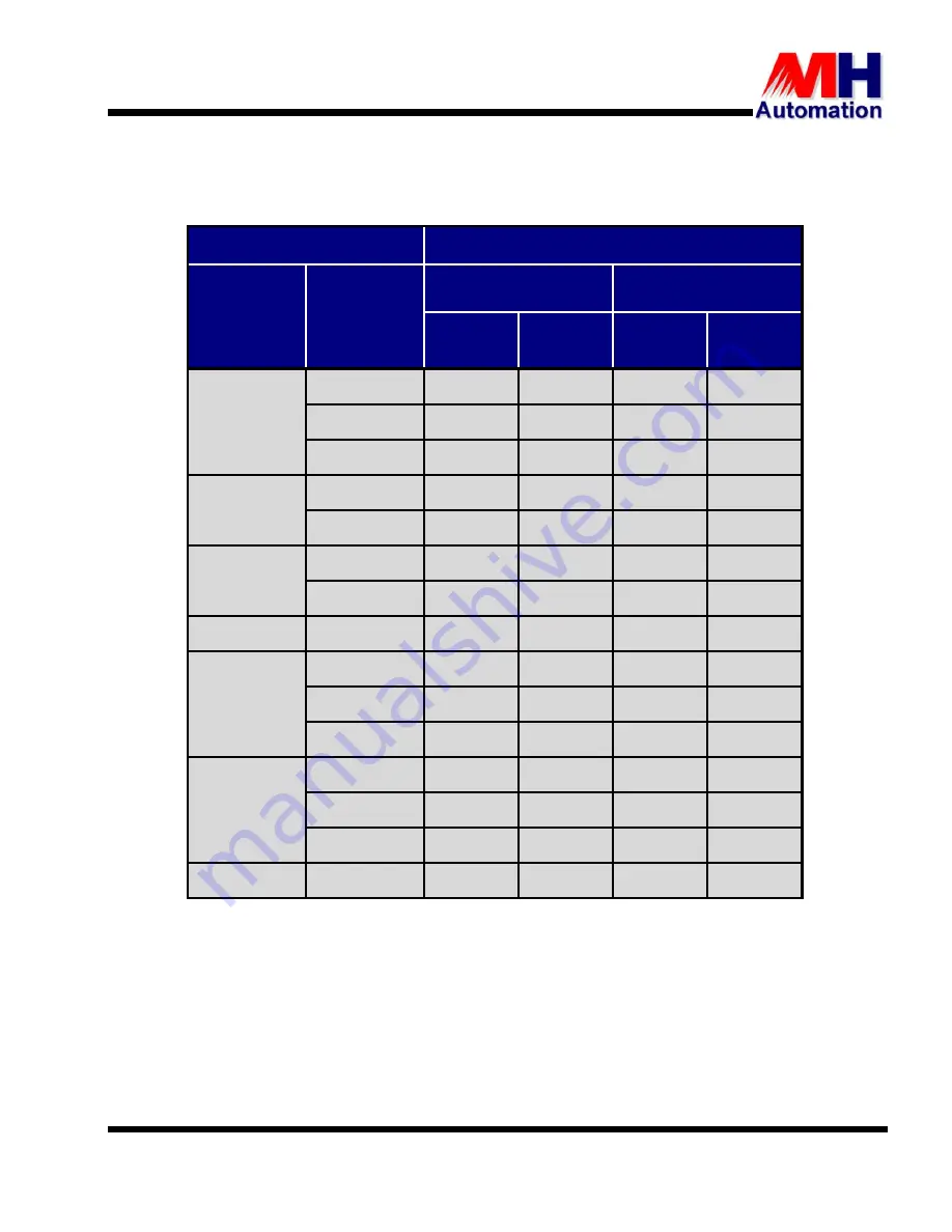
Table 2-4 details the selection of the
maximum stator current
ratings for both hoist and travel in
standard and severe duty applications of the various THYROMAT units.
Table 2-4 : Maximum Motor Stator Current Ratings
THYROMAT - BD
Stator Current
Unit Sizes
Continuos
Current
Ratings at
60
°
C
Hoist
Travel
Standard
Duty
Severe
Duty
Standard
Duty
Severe
Duty
M100
25 A
20.5
A
17.5
A
22.5
A
20.5
A
30 A
25
A
21
A
27
A
25
A
60 A
50 A
43A
55 A
50 A
M150
100 A
83 A
71 A
90 A
83 A
150 A
125 A
107 A
136 A
125 A
M350
200 A
166 A
143 A
181 A
166 A
350 A
291 A
250 A
318 A
291 A
M500
400 A
333 A
285 A
363 A
333 A
M1000
500 A
416 A
357 A
454 A
416 A
700 A
583 A
500 A
636 A
583 A
1000 A
833 A
714 A
909 A
833 A
M2000
1200 A
1 000 A
857 A
1 090 A
1 000 A
1500 A
1 250 A
1 071 A
1 363 A
1 250 A
2000 A
1 666 A
1 428 A
1 818 A
1 666 A
M2500
2500 A
2 080 A
1 780 A
2 270 A
2 080 A
2.5. PRINCIPLE OF OPERATION
The THYROMAT is connected in series with the stator supply voltage.
The control unit varies the stator voltage of the slip-ring motor by adjusting the firing angle of the
inversely connected (parallel) thyristors in each of the three phases. The motor torque is proportional to
the square of the stator voltage (T
V
2
- where T is the motor torque and V is the stator voltage). The
speed of the motor is measured by the frequency of the rotor. Reversing the direction of motor rotation
is achieved by switching externally mounted reversing contactors at zero current.


