SECTION 3 - M. FRAME, ADJ. RING, TRAMP REL. & CLRNG JACK ASSY
MP SERIES CONE CRUSHER TECHNICAL REFERENCE MANUAL
3-29
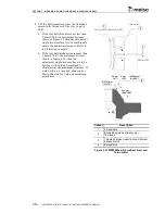
Figure 3-23 Clamping Ring Capscrews
4. Make sure the clamping circuit is
depressurized by opening the clamping
cylinder needle valve located at the power
unit. Make sure the pressure gauge in the
clamping circuit reaches zero (0) pressure.
Then disconnect the hose that runs from the
adjustment ring up through the clamp ring
from the elbow.
5. Install a M36 ring bolt in each of the two
tapped holes in the clamp ring and carefully
lift the clamp ring and the clamping
cylinders off the adjustment ring.
6. The adjustment cap seal is a continuous
rubber ring and is detached by removing the
attaching capscrews and hex nuts. The new
seal is positioned around the perimeter of
the dust shell. Metal clamp segments are
positioned at the top on the dust shell and
the parts are held together by capscrews and
hex nuts shown in Figure 3-20.
7. If the adjustment ring is to be taken off the
frame, all the tramp release cylinders have
to be removed from the Crusher as described
under
Tramp Release Cylinder and
Accumulator Removal
in this section. Also
disconnect the following hoses, plug or cap
all open ports:
MP1000
a. The clamping cylinder supply hose at the
adjustment ring.
b. The two hydraulic motor supply hoses
and the brake supply hose from the tees
on the adjustment ring.
MP800
a. The four supply hoses, for the hydraulic
motors, brake and clamping cylinders, at
the manifold block mounted on the
adjustment ring.
8. Attach shackles and lifting slings to the lift
lugs, four on the MP1000, three on the
MP800, located on the outside diameter of
the adjustment ring. Refer to Figure 3-7 and
Figure 3-20.
9. Carefully lift the adjustment ring off the
main frame and set on blocking.
Callout
Description
1
Clamping ring capscrew
2
Spacer
3
Dust shell
4
Clamping ring
5
Adjustment ring
6
Washers (MP800 only)
2
3
6
1
4
5
Summary of Contents for MP1000
Page 1: ...Nordberg MP Series Cone Crusher ...
Page 2: ......
Page 4: ......
Page 6: ......
Page 8: ......
Page 64: ...SECTION 0 SAFETY 0 56 MP SERIES CONE CRUSHER TECHNICAL REFERENCE MANUAL ...
Page 66: ......
Page 74: ......
Page 154: ...Countershaft and Countershaft Box Callout Description 1 Countershaft 2 Countershaft box 1 2 ...


