SECTION 3 - M. FRAME, ADJ. RING, TRAMP REL. & CLRNG JACK ASSY
MP SERIES CONE CRUSHER TECHNICAL REFERENCE MANUAL
3-17
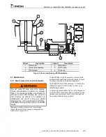
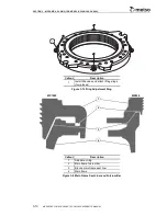
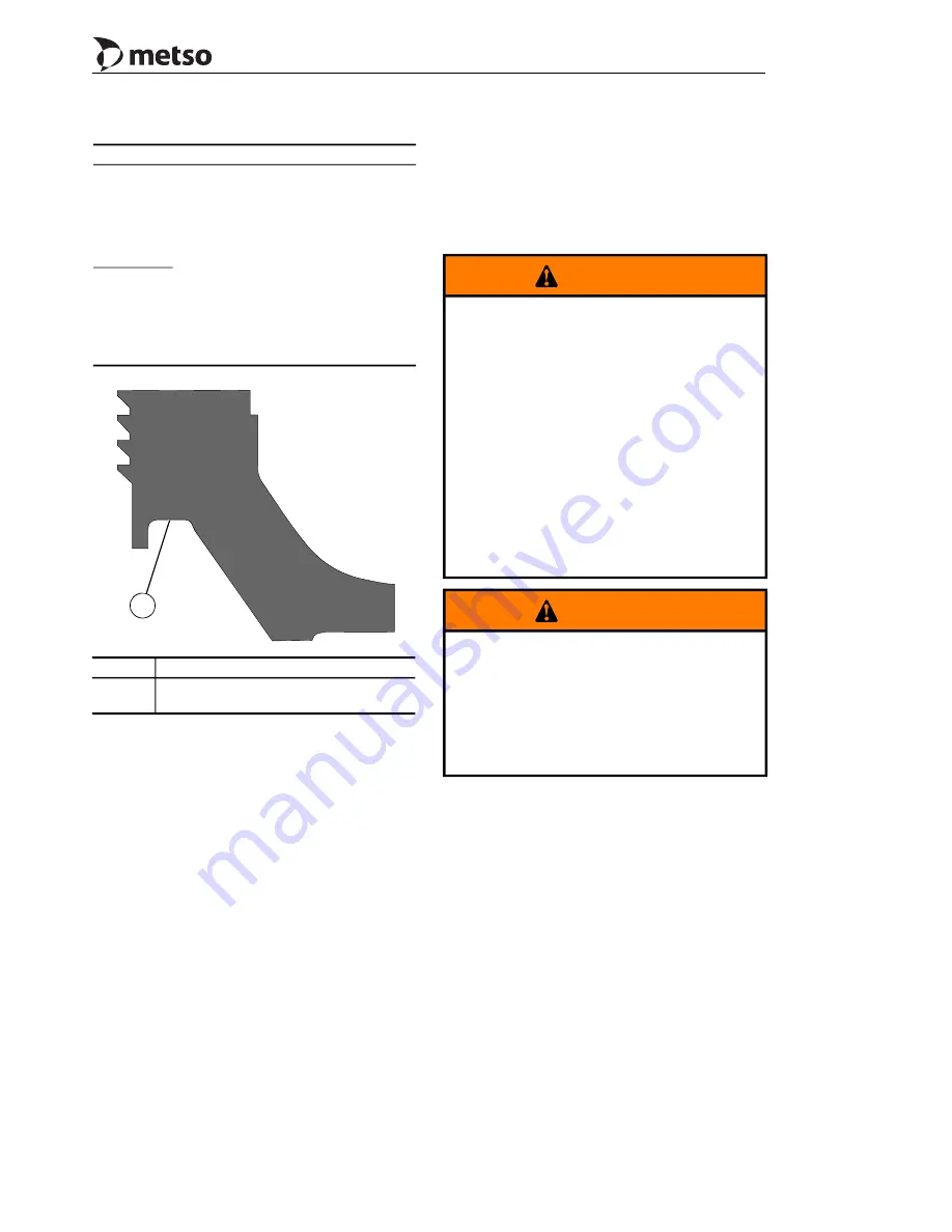
Figure 3-14 MP800 Adjustment Ring Fulcrum
Surface
3.4.4 Tramp Release Cylinder and
Accumulator Removal
A leaking cylinder requires immediate attention.
External leakage will be visible by oil and dirt
accumulations on the cylinder. Oil leakage at the
cylinder will result in loss of pressure at the release
system pressure gauge. If the system loses pressure
and requires repeated recharging, an oil leak should
be suspected.
Due to the size and weight of the accumulator it is
necessary to remove and install the tramp release
cylinder and accumulator as an assembly. For
safety it is also recommended to release the
nitrogen pressure in the accumulator prior to
removing the tramp release cylinder and the
accumulator from the Crusher. Refer to
Accumulator Replacement
later in this section for
the process of safely releasing the nitrogen pressure
from the accumulator.
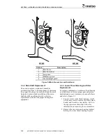
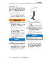
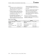
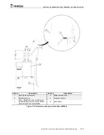
Remove a leaking cylinder for replacement or
repair as follows (refer to Figure 3-12):
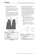
1. Index the drive ring so that one of the two
50 mm (1.97") diameter holes is directly
above and in line with the tramp release
cylinder that is going to be removed for
servicing. On more recent Crushers, these
holes have been provided in the drive ring
for handling the tramp release cylinder, if
your Crusher does not have these holes in
the drive ring contact Metso Product
Support Department for instructions on how
and where to add the holes.
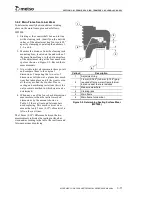
Example MP800:
2.0 mm
(0.080")
–
Minimum clearance required between
new main frame fulcrum bars and
adjustment ring fulcrum surface from
Figure 3-10
–1.0 mm
(0.040")
– Thickness of clay balls
1.0 mm
(0.040")
–
The amount of material to be
machined off the adjustment ring
fulcrum surface to obtain minimum
distance from Figure 3-10. Refer to
Figure 3-14 for location of
adjustment ring fulcrum surface.
Callout
Description
1
Adjustment ring fulcrum surface (this
area to be machined)
1
WARNING
Prior to performing maintenance work on
any part of the Crusher, lockout and tag all
electrical power supplied to the power unit
and Crusher and release stored pressure in
all hydraulic circuits. Death or serious injury
may result if the Crusher systems are
activated while maintenance work is being
performed. Turn the POWER OFF/ON
switch located on the local control station to
the OFF position and lock out and tag the
power supply to the power unit and Crusher.
Depressurize the hydraulic circuits by
opening (turn counter-clockwise) the needle
valves located at the hydraulic power unit
cabinet. This will vent the pressurized oil in
the hydraulic circuits back to tank.
WARNING
Do not attempt to disconnect any of the
hydraulic connections without first insuring
that the system has been depressurized.
Disconnecting a hose while under high
pressure is dangerous due to the high
velocity of the escaping oil and due to the
possibility of being struck by the free end of
a whipping hose.
Summary of Contents for MP1000
Page 1: ...Nordberg MP Series Cone Crusher ...
Page 2: ......
Page 4: ......
Page 6: ......
Page 8: ......
Page 64: ...SECTION 0 SAFETY 0 56 MP SERIES CONE CRUSHER TECHNICAL REFERENCE MANUAL ...
Page 66: ......
Page 74: ......
Page 154: ...Countershaft and Countershaft Box Callout Description 1 Countershaft 2 Countershaft box 1 2 ...

