SECTION 3 - M. FRAME, ADJ. RING, TRAMP REL. & CLRNG JACK ASSY
MP SERIES CONE CRUSHER TECHNICAL REFERENCE MANUAL
3-19
4. Release the nitrogen pressure from the
accumulator. Refer to
Accumulator
Replacement
later in this section for the
process of safely releasing the nitrogen
pressure from the accumulator.
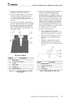
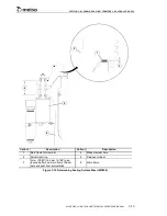
5. Thread an M20 eyebolt into the end of the
cylinder rod. The eyebolt must be turned
down completely so that the shoulder of the
eyebolt is seated on the top surface of the
cylinder rod. The M20 eyebolt used must
have a diameter not to exceed 72 mm
(2.83") in order to pass through the rod nut.
6. Lower a lifting sling from an overhead crane
through the hole in the drive ring and
connect to the eyebolt with a shackle. The
shackle and sling used to connect to the
eyebolt must have adequate capacity and a
width not to exceed 72 mm (2.83") in order
to pass through the rod nut. The lifting sling
must have adequate length to enable the
cylinder to drop to the floor or platform
before the hook on the overhead crane hits
the drive ring.
7. Take up any slack in the lifting sling. If an
overhead crane is not available, scaffolding
can be built to support a chain hoist to
remove the tramp release cylinder assembly.
8. Remove the rod nut and bearing cone from
the threaded end of the cylinder rod.
9. Slowly lower the tramp release cylinder to
the floor or platform and remove the shackle
and eyebolt from the cylinder rod.
10. Remember to remove the rod nut and
bearing cone from the sling above the
adjustment ring.
11. Refer to
Section 12
for tramp release
cylinder re-building instructions.
3.4.5 Tramp Release Cylinder and
Accumulator Installation
Due to the size and weight of the accumulator it is
necessary to remove and install the tramp release
cylinder and accumulator as an assembly.
Install a new or repaired cylinder as follows:
1. Index the drive ring so that one of the two
50 mm (1.97") diameter holes in the drive
ring is above and directly in line with the
mounting location of the tramp release
cylinder that is being installed. On more
recent Crushers, these holes have been
provided in the drive ring for handling the
tramp release cylinder, if your Crusher does
not have these holes in the drive ring contact
Metso Product Support Department for
instructions on how and where to add the
holes.
2. Lock out and tag all electrical power
supplied to the power unit and Crusher and
depressurize the clamping and tramp release
circuits by opening the clamping cylinder
and tramp release cylinder needle valves
located on the side of the hydraulic power
unit at the hose connection area. Verify that
the pressure gauges (PI-1 for the clamping
cylinder circuit and PI-2 for the tramp
release circuit) read zero pressure.
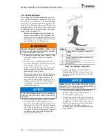
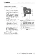
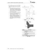
3. With the tramp release cylinder on the floor
or platform directly below its mounting
location on the adjustment ring, slide the
lower bearing cone onto the cylinder rod
with the bevel pointing away from the
cylinder and seat it on the cylinder head.
Then coat the bevel of the cone with “never
seize”. Note that the release cylinder boss
and the lower bearing cup should still be in
place on the underside of the main frame.
WARNING
Provide safe work platforms for all
maintenance and operational requirements.
Death or serious injury may result from a fall
from an unstable or inadequate work
platform. Work platforms must be anchored
to provide adequate stability and must be
structurally able to support the loads
sustained
during
any
maintenance
operation. Workers must also be prepared
with fall arrest harness equipment. Follow all
OSHA, MSHA and site specific guidelines
for the requirements of working from
elevated platforms.
Summary of Contents for MP1000
Page 1: ...Nordberg MP Series Cone Crusher ...
Page 2: ......
Page 4: ......
Page 6: ......
Page 8: ......
Page 64: ...SECTION 0 SAFETY 0 56 MP SERIES CONE CRUSHER TECHNICAL REFERENCE MANUAL ...
Page 66: ......
Page 74: ......
Page 154: ...Countershaft and Countershaft Box Callout Description 1 Countershaft 2 Countershaft box 1 2 ...

