MP SERIES CONE CRUSHER TECHNICAL REFERENCE MANUAL
3-1
M. Frame, Adj. Ring, Tramp Rel. & Clrng Jack Assy
S
ECTION
3
3.1 Description
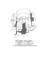
This section covers the main frame, adjustment
ring, tramp release and clearing jack assemblies.
The main frame, which is securely bolted to a
foundation, provides a rigid support for the
remaining Crusher components.
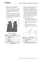
The main frame liners hung from the inside of the
frame as well as arm guards are replaceable and
protect the inside of the frame from wear. Another
replaceable item is the eccentric counterweight
guard, located around the outside of the gear well
that protects the outside diameter of the eccentric
counterweight from excessive wear during
operation.
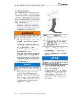
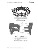
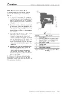
The adjustment ring, which sits on top of the main
frame, is threaded on its inside diameter to provide
the means of adjusting the bowl assembly. A
threaded clamp ring on top of the adjustment ring is
forced upward by a series of hydraulic clamping
cylinders positioned between the clamp ring and
the adjustment ring. The clamp ring holds the bowl
tightly against the slanted side of the adjustment
ring threads preventing the bowl from shifting or
rotating during the crushing process. A dust shell
attached to the adjustment ring shields the clamping
cylinders and bowl threads from outside
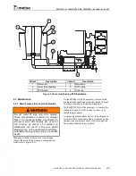
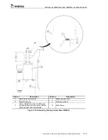
contaminants. Hydraulic (Tramp) release cylinders
which extend between the main frame and the
adjustment ring, hold the adjustment ring firmly to
the main frame against normal crushing forces.
Excessive forces created by improper operation or
by passing an uncrushable object will pull the
cylinder rod upward. Oil will be displaced from the
upper cylinder chamber into the accumulators
further compressing the nitrogen gas within the
accumulator. Once the overload has passed and
crushing forces normalize, the compressed nitrogen
will return the oil to the cylinder, the cylinder rods
will retract and the adjustment ring will again seat
itself on the main frame. Alignment pins attached
to the main frame project upward through holes in
the adjustment ring to guide the ring back to its
original position.
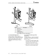
A thrust bearing is bolted to the main frame around
the base of the main shaft. It supports the weight of
the eccentric assembly. Two RTDs are field
installed to monitor the temperature of the oil
exiting the lower end of the eccentric bushing.
These RTDs are located just inside the inner
diameter of the lower thrust bearing.
Shims inserted under the thrust bearing determine
gear and pinion backlash and root clearances.
A molded, nonmetallic U-seal, cemented into an
annular groove around the perimeter of the gear
well, engages a molded T-seal attached to the
counterweight providing a labyrinth type seal that
protects the gear, pinion and bearing surfaces from
dust infiltration. The labyrinth seal surfaces do not
contact during normal operation.
The stationary main shaft serves as a support for the
socket and provides a spindle around which the
eccentric revolves.
3.2 Assembly Instructions
3.2.1 General
The main frame, adjustment ring and tramp release
components will be shipped disassembled. For
assembly of main frame components, follow the
procedures in the
Maintenance
portion of this
section.
3.2.2 Crusher Installation
If the Crusher is to be placed directly on a concrete
foundation, the main frame must be grouted into
place. If a sole plate is to be placed on a concrete
foundation, for mounting the Crusher, it also has to
be grouted into place. Use a high performance
epoxy grouting. For the type of epoxy grouting and
procedure, refer to the epoxy grouting technical
sheets that were furnished with the crusher
installation drawings. If the technical data sheets
are not available, contact the factory.
If the Crusher is to be placed on a steel structure,
the main frame must be shimmed into place due to
warpage or irregularities of the steel structure.
Contact Metso Minerals for structural and
machining requirements.
To install the Crusher on a steel structure, proceed
as follows:
1. Remove all weld slag and spatter from the
top of the steel structure in those areas that
would be under the four main frame
machined mounting pads.
2. Torch cut four spacers, to the same shape, or
contour, as the machine main frame
mounting pads. The spacers should be 6 mm
(0.25") thick with a hole to clear the crusher
anchor bolts. Then place the spacers over the
Summary of Contents for MP1000
Page 1: ...Nordberg MP Series Cone Crusher ...
Page 2: ......
Page 4: ......
Page 6: ......
Page 8: ......
Page 64: ...SECTION 0 SAFETY 0 56 MP SERIES CONE CRUSHER TECHNICAL REFERENCE MANUAL ...
Page 66: ......
Page 74: ......
Page 154: ...Countershaft and Countershaft Box Callout Description 1 Countershaft 2 Countershaft box 1 2 ...


