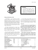
E-CELL display
G
WARNING
There is a risk of an accident if you accelerate
or overtake when the power output of the
drive system is reduced.
You should therefore adapt your driving style
and drive particularly carefully. Charge the
high-voltage battery at a charge station imme-
diately.
X
Start the drive system (
Y
page 128).
E-CELL display
:
shows the available power
of the drive system.
Under normal operating conditions, E-CELL dis-
play
:
is in the maximum range.
The power output available may deviate from
the maximum range in the event of:
R
very high or low outside temperatures
R
very high performance requirements for a lon-
ger period of time
R
very low charge status of the high-voltage
battery
R
a malfunction in the drive system
The reduced power output can be improved by
charging the high-voltage battery (
Y
page 134).
Power display
Power display
:
contains two areas:
R
Area above 0
Here, the current amount of power that the
drive system is feeding to the wheels is dis-
played.
R
Area below 0
Here, the vehicle's recuperative power in
overrun mode is displayed.
If the needle for the power display is in the OFF
position, the vehicle is not ready to drive
because:
R
the drive system has not yet started
R
the charging cable is still connected to the
vehicle socket
R
there is insufficient power available from the
high-voltage battery
R
the vehicle's high-voltage electrical system is
malfunctioning
When the drive system is started, the needle in
the power display moves to position 0. The dis-
play
Ready
Ready
appears in the lower multifunction
display. The vehicle is ready to drive.
The boost area for maximum acceleration can
be reached using kickdown (
Y
page 131).
The braking performance of the electric motor
using recuperative braking is, in some operating
modes, either reduced or not effective:
R
when the charge status of the high-voltage
battery increases
R
if the high-voltage battery is not yet at a nor-
mal operating temperature
R
when driving close to the maximum speed
R
when the vehicle is almost stationary
R
in transmission position N
R
during and after ESP stability control
Displays and operation
173
On-
boar
d
comp
ut
er
and
dis
pla
ys
Z
Summary of Contents for B 250 e 2015
Page 2: ......
Page 3: ......
Page 289: ...286 ...
Page 290: ...287 ...
Page 291: ...288 ...
Page 292: ......
Page 293: ......


