background image

SECTION 2 

TROUBLESHOOTING 


23 


Toolbox System Status Messages 

Displayed, in 

red

, in the M Series Toolbox utility. 

SYSTEM STATUS 

PROBLEM 

SOLUTION 

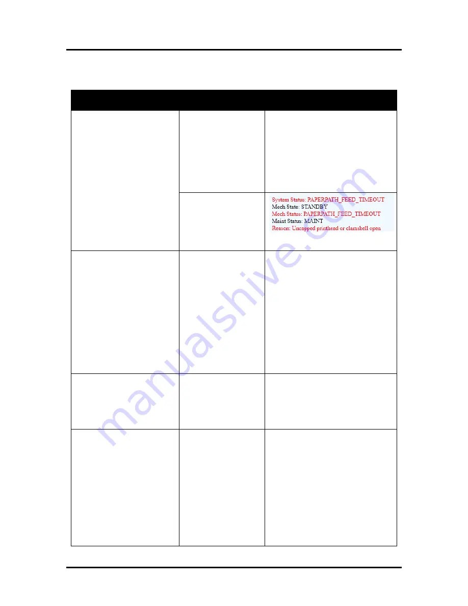
PAPERPATH_FEED_TIME
OUT 
 

Out of Paper 
Media is not reaching 
the print engine. 
Hesitation in media feed. 

Load media into printer and press the 
PAPER/RESUME button. 
If media is present; check/adjust the 
guides and separators. 
Tip: It is also possible to get this error if 
the media jams after reaching the 
Paperpath Exit sensor, and the trailing 
edge is still in the Entry sensor. See 
below. 


Possible Paper Jam; if 
error is shown in 
combination with 

“Reason: Uncapped 
printhead or clamshell 
open”

 message. 


See “Paperpath_Paperjam” solutions. 

PAPERPATH_PAPERJAM 

Paperpath: Entry:Yes   Exit:Yes 
or 
Paperpath: Entry: No   Exit:Yes 
or 
Paperpath: Entry:Yes    Exit:No 
 
No = not blocked 
Yes = blocked (interrupted)


Paper Jam 
Media jam detected. 
 
Printer has detected that 
one of the media sensors 
is blocked (interrupted). 
 

Carefully open the Clamshell, remove 
jammed Media from printer and close 
the Clamshell. The System Status 
message in 

red

 should go away. 

The toolbox “Paperpath” line should 
change to:  
Paperpath: Entry: No  Exit: No 

After you clear the jam you can; 
Press RESUME button to continue 
printing. 
Press the CANCEL button to cancel the 
job, and then manually clear the job 
from the computer’s print queue. 

DOOROPEN_FRONT 

Printer has detected that 
the “Clamshell” is open. 
Sensor cable P2002 
unplugged? 

Verify that the “Clamshell” is closed 
and securely latched at both sides. 
If closed; check the clamshell latch & 
switch. Use Scan Sensors feature in the 
Toolbox Service Menus to test 
clamshell switch. 

DATA_PATH_UNDERRUN 

Media is not making it 
from the entry sensor to 
the exit sensor in the 
appropriated time. 
Possible issue with 
format or orientation of 
job being sent. 
 
Possible issue with 
Encoder in Print Engine. 
Resistance to Print 
Engine drive or media 
movement. 

Check/clean transport rollers. 
Check/clean sensors.  
 
 
Try changing the orientation setting in 
the software/driver or setting a different 
media size. 
 
Check/clean encoder and wheel. 
Check for mechanical issues that may 
cause resistance to transport or media 
movement. 

Summary of Contents for AS-1180C

Page 1: ...MACH 8 HJ AS 1180C HIGH CAPACITY DIGITAL COLOR PRINTER SERVICE MANUAL Rev 05 27 14 PRELIMINARY ...

Page 2: ...ts that are controlled by wall switches or shared with other equipment Make sure there is no strain on the power cord caused by jamming it between equipment walls or furniture DO NOT remove covers Covers enclose hazardous parts that should only be accessed by a qualified service representative Report any cover damage to your service representative This machine requires periodic maintenance Contact...

Page 3: ...28 SECTION 3 Toolbox Service Features 30 Using the Printer Toolbox 30 Service Menu 32 SECTION 4 Disassembly Assembly Procedures 36 Printer Basic Disassembly 36 Service Disassembly Procedures 36 Left hand Side Operator Side Covers 37 Right hand Side Non Operator Side Cover 38 Replacing the Feed Sensor 39 Adjusting the Feed Sensor 40 Replacing Feed Motor Drive Belt or Motor 41 Replacing the Clutch 4...

Page 4: ...der the Clamshell Assembly 127 Removing Clamshell Assembly 127 Replacing Exit Sensor 127 Replacing Label Web Sensor 128 Replacing Service Station Sled Printed Circuit Boards 129 Replacing Wiper Motor Flex Cable PCA 129 Replacing Service Station Lifting Arms 130 SECTION 5 Maintenance 138 Maintenance Schedule 138 Replacing the Ink Tanks 139 Cleaning Ink Tank Contacts 140 Cleaning Replacing the Print...

Page 5: ...Surfaces 161 Printing Platen Surface 161 Cleaning the Ink Revolver Couplings 163 Preparing Printer for Transport 164 Local relocation 164 Remote relocation or shipping 164 Lubricating the Service Station 166 Reinstalling or Replacing the Service Station 168 Lubricating the Media Table Lift Assembly 171 Appendix A Ink Delivery System IDS 173 Theory of Operation 173 Index 175 ...

Page 6: ...ridge M5PRINT N Known good Service Station 123 2483 Lint free cloths Distilled or Deionized water Computer Win XP Vista Win 7 with USB 2 0 port and USB cable It would be best if the computer system has been previously interfaced and tested with a Digital Color Printer That way they should have documents or jobs already setup to test with printer drivers loaded toolbox loaded Operations CD contains...

Page 7: ...must also be installed or the Toolbox will not open Windows 8 8 1 is supported in Desktop Mode only Metro Apps applications for the Windows 8 8 1 environment only are not supported How to check your system for the minimum system requirements shown above Right click on My Computer and select Properties The system information including Operating System Processor Info and Memory info will be displaye...

Page 8: ... pinched color tube finger on Forwarding Roller Guide Assembly may be pinching tube check related Ink Tank and or the system may need to be re primed Please refer to the Troubleshooting section for information on correcting these issues Try removing air bubbles from printhead and system using the Toolbox utility feature Circulate Ink while lightly tapping on the ink tubes and printhead cartridge N...

Page 9: ...sible Solutions Press the Full Clean Printhead button located in the Toolbox User Interface screen and lightly tap on the ink tubes and Printhead Cartridge as the system is circulating ink This can help dislodge air bubbles within the Printhead and Ink Tubes Note It is not a problem if air bubbles accumulate in the ink hoses at the non operator side of the printhead since this is the outgoing side...

Page 10: ...zles are normally due to the nozzle reaching its end of life 50 000 000 ejections Possible Solutions Press the Full Clean Printhead button located in the Toolbox User Interface screen Manually clean the printhead nozzles using distilled water and a lint free cloth Set the following Toolbox features to defaults to improve increase head maintenance routines KWS Setting Light and Mid Job Servicing De...

Page 11: ...e the wiper roller Ink flooding on the nozzle plate due to printer not being level Ink flooding on the nozzle plate due to excessive back pressure in the ink system Wiper Roller is not being cleaned properly by the system This can also occur if there is a problem with the squeegee blade in the Wiper Motor Assembly The squeegee blade and squeegee roller are responsible for removing ink and debris f...

Page 12: ...tilled water to remove excess ink If possible rotate the media and image 90 270 or 180 degrees Sometimes the direction of feed and the mechanics of how the media is driven through the printer can have an effect Allow the printer to sit powered on for 2 3 hours to give it time to remove excess ink from the wiper roller or replace the wiper roller Use a more suitable media flat and uniform in thickn...

Page 13: ...amount of ink being sprayed onto the media by setting the print quality to Normal Spraying less ink will improve the drying time Reduce the print speed to provide more drying time If you are already printing in Normal Print Quality you can select check the half speed box located under the Print Quality selection in the M Series Driver Use a more inkjet suitable media NOTICE It is OK to run the Qui...

Page 14: ...ng Solution Try printing on a thicker piece of media i e 40lb paper If problem does not occur on heavier material the media you are feeding may be too flimsy Problem Damaged Printhead nozzle surface scratched from improper manual cleaning or dirty damaged wiper roller Solution Only use distilled water and a non abrasive lint free cloth to manually clean the printhead Replace the wiper roller at th...

Page 15: ...re Print Engine is level Replace Ink Tank To avoid damaging additional Ink Tanks please see section titled Replacing The Ink Tanks To help improve Ink Level estimation accuracy make sure the firmware is up to date and try to minimize manual cleaning printhead Ink Level status is displayed as 0 but there is still ink in the Tank Toolbox System Status is displaying Ink_Out_X X color or multiple Syst...

Page 16: ...itioning If problem persists refer to section titled Color Mixing Issues Use inkjet suitable media Make sure the Print Engine is level Make sure to power down the printer using the ON OFF button before shutting off the Main Power Switch Thin crisp vertical line s of missing color Clogged printhead nozzle s Electrical failure or poor electrical connection at printhead Clean the Printhead Reseat the...

Page 17: ...way Try removing it Check ink tubes Is the Forwarding Roller Guide Plate pinching tubes Replace Ink Tank s See Service Menu Commands Help nvm_hw settings Check to be sure Wiper_motor E and Pump_motor B Replace the Printhead Check clean Sensor board on Dual Pinch Valve Replace Ink Valve Ink leaking from the printhead nozzles Printer not level Excessive back pressure within ink system caused by prin...

Page 18: ...iling edge To help keep nozzles from drying clogging all nozzles of the printhead are purged between each page Check adjust media feed setup Check for proper install of Forwarding Roller Guide Assembly Check for obstruction within the Print Engine Rotate media and image so hole in media does not travel over the Paperpath Sensors Adjust the Purge Bar Position value located in the User Interface Men...

Page 19: ...to illuminate Problem within printer ON OFF Button Fuse Receptacle Power Supply Main PCB Try powering up engine using small red button located below power connection on Main PCB If it powers up then there is an issue with the ON OFF button Disconnect Power Cord and check Fuse in Receptacle Replace bad Fuse If Fuse is OK reconnect power and check output on Receptacle Replace receptacle if bad If Re...

Page 20: ...t seated properly Debris build up on blade and rollers increasing friction Bad wiper roller motor Verify ribbon cable and motor cable are properly connected to board on side of Service Station and at back of SS slot Reseat squeegee blade Clean rollers and blade Replace Wiper Motor Assembly or Service Station Color mixing occurs after wiper roller performs a cleaning Wiper Roller is over saturated ...

Page 21: ...stem does not meet minimum requirements Java Microsoft NET Framework not installed or version not supported Printer s Toolbox Embedded Web Server not responding Firewall is blocking communication with Toolbox System is hung up USB Cable connection issue Check that computer system meets minimum requirements Install Update Java to version 6 Install Microsoft NET Framework 3 5 32 bit or 4 64 bit Clos...

Page 22: ...tor not driving No power Readjust Side Guides Check that power is ON Main Power Switch and ON OFF button and that the power cord is plugged in Check Adjust Separators and Media Thickness See Setting up the Feed Maximum thickness is 0 020 Check for mechanical issue Loose sprocket broken belt etc Check Test Clutch Check Test Motor See Power Problems in this Section Jams Paper path obstruction Paper ...

Page 23: ...nection at I O board Improper Connection of J703 at Main PCB Damage to cable that runs between S4 on I O board to J703 on Main PCB In the Max Throughput mode the printer will feed 1 or 2 blanks at end of job Set to Safe Feed to eliminate this issue Check Clean Replace Feed Sensor and or Reflector Check Connections at I O board Check to be sure J703 at Main PCB is connected to proper socket Repair ...

Page 24: ...al contacts Reinsert printhead Replace printhead Multiple Inks Low Reorder Ink Multiple Ink Tanks Out Replace empty Ink Tanks Multiple Ink Tanks are missing Insert missing Ink Tanks Clean electrical contacts and re seat Ink Tanks Multiple Unauthorized Ink Tanks Remove and re insert Ink Tank Replace Ink Tank Ink Tanks must be purchased from authorized supplier for this printer model Paper Jam Remov...

Page 25: ...ammed Media from printer and close the Clamshell The System Status message in red should go away The toolbox Paperpath line should change to Paperpath Entry No Exit No After you clear the jam you can Press RESUME button to continue printing Press the CANCEL button to cancel the job and then manually clear the job from the computer s print queue DOOROPEN_FRONT Printer has detected that the Clamshel...

Page 26: ...eplace the Ink Level PCA Sensor Board MAINTENANCE_BUSY Printer is performing maintenance No action is required Wait for printer to finish Printer is waiting to perform maintenance if error is shown in combination with Reason Uncapped printhead or clamshell open and there is no maintenance activity noise coming from printer Remove media from print engine See Paperpath_Paperjam solutions If problem ...

Page 27: ...ents was not properly registered at the expected position If the Service Station was just installed check to be sure it was installed properly Depending on the reason check the associated component and related sensors Using the Scan Sensors page in the Toolbox perform the toggle test on the Sensor responsible for registration of the failed mechanical component position Lifter Arm Sensor is dirty o...

Page 28: ...printhead and check clean contacts then reinstall printhead Replace printhead Refer the appropriate sections in the operations manual for removing and installing the printhead cartridge If problem check cable connections between Pen Board and Main PCB J2001 J250 260 P250 260 Make sure cables were not mistakenly swapped PRINTHEAD_UNPRIMED Printhead priming process has failed Ink delivery issue If j...

Page 29: ...ice Station flows through the wicking material and out the hole located on the bottom of the service station In some cases the wicking material that hangs out this hole may not be directed into the trough located below the Service Station If this occurs ink will build up on the base of the Service Station Slot Check to be sure the wick is hanging in the waste ink trough Ink Accumulating in the Bod...

Page 30: ...ing due to improper Media Thickness adjustment worn sheet separators improper media loading or media adhesion media that is stuck together due to static energy or coating 2 Damaged media such as dog eared turned down corners curled or bowed media 3 Media that is not stiff enough may not be usable Media that meets Postal stiffness requirements for automated feeding is acceptable in the Digital Colo...

Page 31: ...ase and lift the two latches B one on each side of the Print Engine Clamshell at the same time to raise the Print Engine Clamshell C Clear the jam then carefully lower and relatch the Print Engine Clamshell Close the Top Cover CAUTION HOLD ONTO BOTH LATCHES WHEN OPENING AND CLOSING THE PRINT ENGINE CLAMSHELL TO PREVENT DAMAGE DO NOT ALLOW THE CLAMSHELL TO DROP OR SLAM CLOSED TO PREVENT DAMAGE TO T...

Page 32: ... printer status monitor ink usage perform diagnostic checks print reports and run maintenance tasks on the Printer from your computer To open the Toolbox Open the Start Menu then click on Toolbox When the User Interface window opens you will find a series of Menu Options you can click on at the lower left of the screen You can check the Printer Status in the upper left part of the screen ...

Page 33: ... then restarts automatically to complete the installation Diagnostics From this screen you can see the current status of your Printer You can also Print Sample Page Prints type and color bands to check print quality Print Configuration Page Displays the current configuration of the Printer including Firmware Version Network Connection Printer Serial Number and more Print Diagnostic Page Displays b...

Page 34: ... Settings to enter the correct settings for your network 2 Connect Ethernet cable to Network Port on Rear Panel of Printer Service Menu For authorized service personnel only Provides access to more advanced Printer Control and Maintenance menus Enter password to view the Service menus ...

Page 35: ...Printer Status column You can also Print Sample Page Print Configuration Print Diagnostics Print Demo Page Print Ink Channels and Print Color Bars without returning to the Diagnostics screen You can also return the Printer to the default settings by pressing the Reset to Factory Settings button Printer Control Configuration Screen Allows you to make fine adjustments as to how a job is fed into and...

Page 36: ...Submit in the User Interface screen to bypass the Exit Sensor Clamshell Switch Clamshell Open 1 Clamshell Closed 0 Lifter Arm Up 1 Down 0 Sled Index Cap Position 0 Print Wipe Positions 1 Sled Home False 0 True 1 Paper Feed Sensor Covered media present sensor dirty 1 Uncovered no media 0 Valve Position Displays the operating positions of the Dual Pinch Valve OpenAir OpenInk and Closed Unknown will ...

Page 37: ...AL OPERATION 35 Printer Commands Help Screen Provides a list and descriptions of available EWS service commands Clicking Exit Service Menus closes the Service Menu options and takes you back to the User Interface screen ...

Page 38: ...N THE PRINTER BEFORE CONNECTING OR DISCONNECTING ANY WIRING HARNESSES OR CABLE CONNECTIONS TO AVOID SERIOUS SHOCK OR INJURY CAUTION ALWAYS USE APPROPRIATE PERSONAL PROTECTION EQUIPMENT PPE DISPOSE OF ALL MAINTENANCE WASTE IN ACCORDANCE WITH LOCAL REGULATIONS CAUTION USE ELECTROSTATIC DISCHARGE ESD PROTECTION WHEN WORKING AROUND ELECTRONIC DEVICES USE STATIC FREE WORKSTATIONS WHEN UNIT COVERS ARE R...

Page 39: ...ew at the top front of Cover and 2 screws under the lower edge of the Cover access by opening the Storage Compartment Door 3 Reassemble in reverse order NOTE Make sure that the wires are connected to the correct Control Panel Button Components under Left hand Side Operator Side Covers 1 Ethernet Port Connector 2 USB Port Connector 3 Main Power Connector 4 Service Diagnostic Port 5 Home Position UP...

Page 40: ...top front of the Cover Major Components under Right hand Side Non Operator Side Cover 1 Power Supply 2 Receiving Tray Interface Port 3 Encoder Encoder Sensor 4 Feed Clutch and Feed Roller Assembly 5 Interface Control Board 6 Drive Motor Roller Drive Pulley 7 Network Connector 8 USB Connector 9 Power Switch Fuse 10 Auxiliary Power Receptacle 11 Speed Control ...

Page 41: ...or from the Interface PC Board A Unclip the wire from any mounting clips 3 A Remove 2 screws attaching the Sensor to the Sensor Bracket B Carefully cut wire tie Remove Sensor 4 Install the new Feed Sensor Assembly in reverse order NOTE The new Feed Sensor may have to be adjusted see Adjusting the Feed Sensor on next page ...

Page 42: ...d Sensor If the lights are GREEN OFF or ORANGE perform Steps 2 4 If the lights are ORANGE GREEN perform Steps 3 4 2 Use a small plastic flat screwdriver to slowly turn the potentiometer at the bottom of the Sensor clockwise until the lights turn ORANGE GREEN Continue turning the potentiometer just a few more degrees then stop 3 Place a piece of media you regularly use on top of the Sensor and cove...

Page 43: ...nd the Encoder Sensor NOTE To remove the Motor disconnect the wires and remove the two mounting screws CAUTION DO NOT SCRATCH OR OTHERWISE DAMAGE THE ENCODER WHEEL WHEN REMOVING THE MOTOR DRIVE BELT 3 Carefully remove the Motor Drive Belt by lifting it over and around the Encoder Wheel 4 Replace the Belt in reverse order and then adjust the Belt per the adjustment instructions in Section 4 Replaci...

Page 44: ...the two standoffs B Remove the Encoder Sensor by carefully moving the Sensor down and away from the Encoder Wheel NOTE Be very careful not to damage Encoder Wheel 2 Remove the Encoder Wheel Assembly from the Pull Out Shaft Assembly Remove screw and washer from the center of Encoder Wheel Do not bend or damage the Encoder Wheel during removal 3 To Reinstall Insert screw with washer through the Enco...

Page 45: ...he two thumbscrews A and slide latches back arrows Open the Feed Roller Assembly B 3 Remove Feed Roller Assembly A Remove the E clip End opposite Gear end B Slide Feed Roller Assembly toward the gear end of the shaft C Turn the Roller Shaft so the indent allows the Shaft to fit through the gap in the Feed Head Shell Carefully remove the Feed Roller Assembly ...

Page 46: ...refully pull Switch and Bracket Assembly away from Feed Head Shell 6 Disconnect red wire connector A Disconnect black wire connector B Both located under Right Hand Feed Head Nest Assembly behind Control Panel Remove Switch Assembly 7 Remove screw to remove Switch from Bracket may have to cut cable tie 8 Reassemble in reverse order ...

Page 47: ...two thumbscrews A and slide latches back arrows Open the Feed Roller Assembly B 3 Remove Feed Roller Assembly A Remove the E clip End opposite Gear end B Slide Feed Roller Assembly toward the gear end of the shaft C Turn the Roller Shaft so the indent allows the Shaft to fit through the gap in the Feed Head Shell Carefully remove the Feed Roller Assembly ...

Page 48: ... on top of Feed Head Shell 5 Carefully pull Switch and Bracket Assembly away from Feed Head Shell 6 Disconnect Sensor wire connector Located under Control Panel Remove Switch Sensor Assembly 7 Remove 2 screws to remove Switch Sensor from Bracket may have to cut cable tie 8 Reassemble in reverse order ...

Page 49: ...rews A and slide latches back arrows Open the Feed Roller Assembly B 3 Remove Feed Roller Assembly A Remove the E clip End opposite Gear end B Slide Feed Roller Assembly toward the gear end of the shaft C Turn the Roller Shaft so the indent allows the Shaft to fit through the gap in the Feed Roller side frame Carefully remove the Feed Roller Assembly and set aside ...

Page 50: ... 2 screws at the top of the Cover Then remove the 3 screws from each side of the Cover 2 To Remove Motor Loosen the 4 Motor Assembly mounting screws Move Motor Assembly in slots to remove Belt Now remove the 4 mounting screws NOTE Motor is heavy 3 To Remove Belt Only Loosen the 4 Motor Assembly mounting screws Move Motor Assembly in slots to remove Belt 4 Reassemble in reverse order Remember to in...

Page 51: ... Side Cover by removing the 3 screws on the side of the Cover Remove 2 screws from inside the Storage Door frame Remove 1 screw from the top center of the Cover Remove the Cover 2 Remove the Right hand Side Cover Remove the 2 screws at the top of the Cover Then remove the 3 screws from each side of the Cover ...

Page 52: ...ivider A Remove 2 top screws B Remove 3 screws from each side frame 4 Remove Bottom Media Table Lift Pulley Remove 1 Allen screw and lock washer Slide Pulley off of Shaft 5 Remove the 4 lower Media Table Lift Assembly mounting screws 2 Allen screws per side ...

Page 53: ...SECTION 4 DISASSEMBLY AND ASSEMBLY 51 6 Remove the Bottom Bar Assembly Remove the Belt 7 Reassemble in reverse order Remember to reinstall the Motor Drive Belt ...

Page 54: ...e Cover by removing the 3 screws on the side of the Cover Remove 2 screws from inside the Storage Door frame Remove 1 screw from the top center of the Cover Remove the Cover 2 Remove the Right hand Side Cover Remove the 2 screws at the top of the Cover Then remove the 3 screws from each side of the Cover ...

Page 55: ...Assembly A Remove 4 screws 2 lock washers securing Media Table to the Media Table Brackets located under the Table B Carefully lift rear of Table up be careful not to pull too hard on sensor wiring Cut the cable ties then disconnect the Sensor from the wiring harness Remove the Media Table and set aside ...

Page 56: ...rews 6 Remove the Rear Side Closure located on non operator side A Remove 1 screw and 2 Allen screws Remove 1 screw from the Media Table Bracket Slide Bracket away from the Rear Side Closure NOTE Be careful of any wiring B Remove 2 screws from non operator Side Frame Located below the Main Power Switch Assembly ...

Page 57: ...ttom Divider A Remove 2 top screws B Remove 3 screws from each side frame 8 Loosen Motor Assembly screws Move Motor Assembly in slots to remove Belt 9 Remove Bottom Media Table Lift Pulley Remove 1 Allen screw and lock washer Slide Pulley off of Shaft ...

Page 58: ...bly Bracket Stud B Slide Media Table Lift Assembly up and out of Guide Tracks 11 Reassemble in reverse order Remember to reinstall Belt and reconnect wiring as needed NOTE Lubricate the threaded rods on the Media Table Lift Assembly and the wheel guides on the Printer before reinstalling the Threaded Rod Guard and Rear Side Closure See Lubricating the Media Table Lift Assembly in Maintenance for m...

Page 59: ...rews A and slide latches back arrows Open the Feed Roller Assembly B 3 Remove Feed Roller Assembly A Remove the E clip End opposite Gear end B Slide Feed Roller Assembly toward the gear end of the shaft C Turn the Roller Shaft so the indent allows the Shaft to fit through the gap in the Feed Roller side frame Carefully remove the Feed Roller Assembly ...

Page 60: ... One way Rollers note orientation dimple on hub faces gear end of shaft Reassemble in reverse order Lubricate Feed Roller Shaft before reassembly Remember to reinstall Belt Use the image below for reference 6 Remove the Rear Feed Rollers A Remove E clip at end of the Rear Roller Assembly opposite of Pulley end Slide Belt off of Front Feed Roller Shaft Pulley B Slide Rear Feed Shaft out of Rear Fee...

Page 61: ...e Door frame Remove 1 screw from the top center of the Cover Remove the Cover 2 Remove the Left hand Rear Side Cover Remove 2 screws under the bottom edge of the Cover access by opening the Storage Compartment Door Remove 1 screw from the top center of the Cover 3 Remove the Right hand Side Cover Remove the 2 screws at the top of the Cover Then remove the 3 screws from each side of the Cover ...

Page 62: ...d away from the Encoder Wheel NOTE Be very careful not to damage Encoder Wheel 5 Remove the Encoder Wheel Assembly from the Pull Out Shaft Assembly Remove screw and washer from the center of Encoder Wheel Do not bend or damage the Encoder Wheel during removal 6 Loosen the 2 Feed Drive Motor screws to loosen the Drive Belt 7 Remove Pulley Take Drive Belt off of Pulley Loosen set screw in Pulley Sli...

Page 63: ...de Frame or reach up through the Storage Compartment and pull the Pull Out Roller Shaft toward the non operator side A Make sure the Shaft clears the Delivery Roller Shaft Belt B 10 Remove the Pull Out Shaft Assembly 11 Reassemble in reverse order Remember to reinstall the Delivery Roller Drive Belt ...

Page 64: ...ack arrows Open the Feed Roller Assembly B 3 Remove Hold Down Media Bracket Assembly Release the Media Bracket Assembly by opening the Latch C Slide the Assembly toward the Control Panel D Carefully lift the Assembly up E CAUTION DO NOT BEND PINCH OR CUT THE INK LINES LOCATED DIRECTLY IN FRONT OF THE ASSEMBLY NOTE Make sure Assembly is correctly reinstalled and aligned before starting to print Ass...

Page 65: ...From Operator Side 4 A Unplug the Network Connector if necessary B Remove 2 screws Be careful of Pause Resume Control Button wiring C Remove 1 small mounting screw 5 Nest Head Assembly Remove 1 screw see photo at right and pivot assembly up ...

Page 66: ...Operator Side 6 Unplug Feed Sensor Connector J10 from Interface Board Separate wire from bundle 7 Remove 2 mounting screws access through cutouts in the side frame 8 Carefully remove Delivery Center Plate Assembly 9 Reassemble in reverse order ...

Page 67: ...the Print Engine See Replacing Delivery Center Plate Assembly on previous pages 1 Remove the Delivery Center Plate Assembly 2 Remove Bearing Housing Assembly 2 screws Slide Roller Shaft Assembly toward the opposite side of the Delivery Center Plate Assembly 3 Reassemble in reverse order Take care to reinstall the Belt that drives the Rollers during assembly ...

Page 68: ...nt Side Cover by removing the 3 screws on the side of the Cover Remove 2 screws from inside the Storage Door frame Remove 1 screw from the top center of the Cover 2 Remove the Right hand Side Cover Remove the 2 screws at the top of the Cover Then remove the 3 screws from each side of the Cover ...

Page 69: ...osen the two thumbscrews A and slide latches back arrows Open the Feed Roller Assembly B 4 Remove 4 mounting screws A Remove 2 screws from non operator side Side Frame B Remove 2 screws on control panel side Access through cutouts in side frame 5 Reassemble in reverse order ...

Page 70: ...d Sensors NOTE Wires are labeled for easy reconnection CAUTION DO NOT DAMAGE THE WIRES DURING REMOVAL 3 Remove the 2 screws that attach the PC Board to the Side Frame and remove the PC Board CAUTION MAKE SURE THAT YOU ARE PROPERLY GROUNDED BEFORE HANDLING THE PC BOARD STATIC ELECTRICITY CAN DAMAGE THE BOARD 4 Reassemble in reverse order ...

Page 71: ...r This info is needed in order for the print engine serial number to be programmed into the new board Follow proper static handling precautions Do not pull on the wires to disconnect cables Damage will result Print Engine wiring harnesses are NOT available as spare parts Pull on the connector not the wires to disconnect cables The use of a connector puller tool like the one shown below is suggeste...

Page 72: ...orage Door frame Remove 1 screw from the top center of the Cover Remove the Cover 5 Remove the Left hand Rear Side Cover Remove 2 screws under the bottom edge of the Cover access by opening the Storage Compartment Door Remove 1 screw from the top center of the Cover CAUTION WHENEVER POWERING DOWN UNIT ALWAYS 1 PRESS THE POWER BUTTON ON THE CONTROL PANEL 2 WAIT FOR THE PRINTER TO STOP PROCESSING 3 ...

Page 73: ...ld 7 Remove the Main PCB Cover Using a T10 Torx driver remove the screws that secure the cover There will be 4 or 5 screws depending on print engine version Tip The top section of this cover wraps around the back side of the enclosure Once the screws are removed lift the cover up and then towards you so the cover clears the back side of the enclosure 8 Carefully disconnect all connections from Mai...

Page 74: ...ws 12 Carefully reconnect all connections to the New Main PCB in the order shown on the following pages Please follow this process step by step to be sure each connection is installed into the appropriate socket Tip Triple check that all connections have been properly made before installing the Main PCB Cover CAUTION ALWAYS WEAR A WRIST STRAP THAT IS GROUNDED WHEN TOUCHING ELECTRONIC DEVICES ...

Page 75: ...SECTION 4 DISASSEMBLY AND ASSEMBLY 73 a J1002 Cable J1002 Socket Location Connection ...

Page 76: ...SECTION 4 DISASSEMBLY AND ASSEMBLY 74 b J1000 Cable J1000 Socket Location Connection ...

Page 77: ...SECTION 4 DISASSEMBLY AND ASSEMBLY 75 c J551 Cable J551 Socket Location Connection ...

Page 78: ...SECTION 4 DISASSEMBLY AND ASSEMBLY 76 d J703 Cable J703 Socket Location Connection ...

Page 79: ...SECTION 4 DISASSEMBLY AND ASSEMBLY 77 e P2002 Cable P2002 Socket Location Connection ...

Page 80: ...SECTION 4 DISASSEMBLY AND ASSEMBLY 78 f P2004 Cable P2004 Socket Location Connection ...

Page 81: ...SECTION 4 DISASSEMBLY AND ASSEMBLY 79 g P2006 Cable P2006 Socket Location Connection ...

Page 82: ...SECTION 4 DISASSEMBLY AND ASSEMBLY 80 h J35 Cable J35 Socket Location Connection ...

Page 83: ...SECTION 4 DISASSEMBLY AND ASSEMBLY 81 i P1 Cable P1 Socket Location Connection ...

Page 84: ...SECTION 4 DISASSEMBLY AND ASSEMBLY 82 j P2005 Cable P2005 Socket Location Connection ...

Page 85: ...SECTION 4 DISASSEMBLY AND ASSEMBLY 83 k P2003 Cable P2003 Socket Location Connection ...

Page 86: ...SECTION 4 DISASSEMBLY AND ASSEMBLY 84 l J20 Cable J20 Socket Location Connection ...

Page 87: ...SECTION 4 DISASSEMBLY AND ASSEMBLY 85 m J2001 Cable J2001 Socket Location Connection ...

Page 88: ...SECTION 4 DISASSEMBLY AND ASSEMBLY 86 n J250 Data Cable J250 Data Cable Socket Location Connection o J260 Data Cable J260 Data Cable Socket Location Connection ...

Page 89: ...ON 4 DISASSEMBLY AND ASSEMBLY 87 13 Verify that All Cables Are Installed NOTE There will be 10 open sockets after all cables have been installed Open Sockets J550 J554 J553 J750 J706 J504 J353 J400 J37 P900 ...

Page 90: ...to Main PCB removed in Step 6 16 Reconnect the Power Cord and Interface Cables removed in steps 2 and 3 17 Power the Printer ON and perform a quick Test before you re install side covers Example Demo Page Print from Toolbox or Test Page from M Series Driver Also check that the latest firmware version is installed 18 If Test was satisfactory Reinstall the Side Covers removed in steps 4 and 5 Be car...

Page 91: ...Motor J35 Control Buttons Power Paper Cancel Buttons LED P1 Pen Driver Printed Circuit Assembly MPCA Printhead QAI Bus and 2 5 VDC QAI power 3 3 VDC logic power for Printhead VPOS enable VPOS power good signal DOUT from Printhead Printhead reset lines 5 VDC power for current sense buffer analog current sense line from PPCA pushbutton 2 inputs to MPCA P2005 Ink level PCA Pinch Valve Ink Cartridge Q...

Page 92: ...witch on the Rear Panel Unplug the unit 2 Remove the Left hand Front Side Cover Remove 3 screws on the side of the Cover and 2 screws from inside the Storage Door frame Remove 1 screw from the top center of the Cover Remove the Cover 3 Remove the Left hand Rear Side Cover 2 screws from the edge under the bottom of the Cover access by opening the Storage Compartment Door Remove 1 screw from the top...

Page 93: ...ide Remove Door and set aside 7 Remove Top Cover Remove mounting screw A from left hand side Control Panel side above Main Printed Circuit Board Remove Top Cover and set aside 8 A Unplug 1 USB 2 Network 3 Main Power and 4 PuTTY connectors from Print Engine Circuit Board B Remove the Left Hand Upper Side Frame Remove 3 screws attaching the Upper Side Frame to the Main Side Frame Remove Frame ...

Page 94: ... Motor wiring access from inside the storage compartment NOTE When reconnecting make sure black goes to black connector and red goes to red connector NOTE Due to production changes you may find an interim connation that you can disconnect located between motor and print engine If not you may need to remove the inner sidewall within the storage area to access these motor connections ...

Page 95: ...they won t catch or snag when Print Engine is removed 13 Disconnect the following wires from the Interface Printed Circuit Board located on the non operator side of the Printer Clutch Out J8 S4 J9 14 Disconnect the Encoder connector from the Encoder Printed Circuit Board Pull these wires away from the other wiring so they won t snag when the Print Engine is removed ...

Page 96: ...de in the slot Tighten Knobs fully to lock Print Engine in place Print Engine default position is fully toward the non operator side of the Printer 16 Carefully slide Print Engine out of Printer Print Engine is entire unit including the Ink Station 17 Reassemble in reverse order IMPORTANT WHEN REINSTALLING THE PRINT ENGINE MAKE SURE THAT THE ALIGNING PINS ARE FLUSH WITH EACH OTHER WHEN THE PRINT E...

Page 97: ...ation are removed Removing the Print Engine Base Provides access to parts located underneath the Print Engine 1 Remove Ink Waste Tray from below Ink Tanks and set aside 2 Remove Engine Base Remove 6 T 10 screws 3 on each side of the Print Engine Assembly Set aside for reassembly Print Engine Components Underside A Peristaltic Pump B Dual Pinch Valve C DPCA Board D Buffer Boxes 3 Sets of 2 E Q A Ch...

Page 98: ...Hoses in order shown to hose splice connectors included with kit D IMPORTANT Make sure you know where each Ink Hose connects for reassembly Replacing Dual Pinch Valve Assembly Remove old Valve Assembly A Remove 4 screws that hold Bracket to Chassis B Cut cable tie holding wiring harness to top flange on Bracket Assembly C Unplug the 2 connectors from the Valve Assembly D Disconnect Ink Hoses IMPOR...

Page 99: ...es It is also assumed that the Ink Tanks Ink Waste Tray Printhead and Service Station are removed 1 Use canned air to blow the debris off the two Sensors A B located on the DPV Sensor PC Board 2 As a preventive measure apply a small amount of Super Lube Grease or Teflon based lubricant equivalent to the space between the springs and the DPV Adaptor C D You will need a small brush or toothpick to r...

Page 100: ...e holding wiring harness to top flange on Bracket Assembly C Unplug the 2 connectors from the Valve Assembly IMPORTANT Ink hoses are still attached Carefully pull Pinch Valve Assembly away from chassis without kinking or pulling out hoses Clean Pinch Valve Sensors PC Board 1 Secure the spring loaded shaft using the Dual Pinch Valve Wrench included in Kit Position the wrench exactly as shown NOTE T...

Page 101: ...ush against the Pinch Valve body 5 Install 3 Metal Inserts in the Motor Assembly mounting holes With the rounded end of the insert facing down press the three 3 inserts into the Motor Assembly mounting holes as shown NOTE Insert is self aligning but to ensure it is evenly aligned with the mounting hole and to prevent accidental damage use a flat surface a flat metal bar for example to provide even...

Page 102: ...the Chassis that attach the Circuit Board Bracket to Chassis B Carefully move the DPCA Assembly out to unplug the wire harness connectors NOTE Make sure you know which connectors go with which socket C Remove the 3 screws attaching the DPCA to the Bracket Remove DPCA Board Install in reverse order ...

Page 103: ...the Print Engine or in the Buffer Box simply make sure you have both Put each one in the same color chamber it came from ie blue to blue black to black etc C Push new Buffer Box down onto the ink ports Attach with 2 screws from inside Ink Tank Station Replacing QA Chip Assembly 3 per machine A Each QA Chip Assembly is held in place by 1 screw accessed through center of the Chip Assembly Unplug wir...

Page 104: ...screws attaching the PCA to the Head Board Mount Install in reverse order Removing the Starwheel Assemblies Location Upper Clamshell Open the Print Engine Clamshell to access the two Starwheel Assemblies One is just inside the exit end of the Clamshell the other one is mounted externally on the Clamshell Frame over the Exit Center Plate Assembly The removal procedure is similar External A Remove 2...

Page 105: ...ircuit Board Cover B Remove 2 screws from bottom of Pen Driver Printed Circuit Board bay C Locate and carefully release the 2 black locking tabs holding the Starwheel Assembly to the metal bracket NOTE Locking tabs break easily Remove the Starwheel Assembly Install in reverse order ...

Page 106: ...ch Assembly CAUTION Latches are spring loaded watch that springs don t fly off Replacing the Printhead Lever Latch The Printhead Lever Latch is easily broken if forced open manually Tools Supplies needed nitrile powder free gloves needle nose pliers or tweezers small flathead screwdriver Follow the steps below to replace the Latch Remove the Printhead Latch 1 Go to the Printer Toolbox User Interfa...

Page 107: ...g out from beneath the plastic tab in the housing and remove the Spring Repeat the procedure to remove the second Spring 7 Gently insert a small flathead screwdriver between the blue Printhead Latch Pin and the black plastic hinge A and rotate to pop the Printhead Latch out of the hinge without damaging either piece CAUTION BE CAREFUL Black Plastic Hinge breaks easily Use only gentle pressure when...

Page 108: ...rinthead Latch 3 Repeat Steps 2A and 2B for the left side 4 Remove the Printhead from the protective cap and wipe the Printhead surface according to standard installation procedure then install 5 Restart the Printer 6 Manually close the Printhead Latch until it clicks The Printer will automatically prime and be ready for testing NOTE If the Printhead Latch is closed with the system powered down th...

Page 109: ... Release Printhead to release the Printhead Latch 3 Once the Latch pops up click Shutdown to shut down the Printer 4 Lift the Latch manually to access the Solenoid and Latch Support Base 5 Remove the Printhead Cartridge by tilting it toward the ink lines then carefully lifting it out of the Printhead Compartment Place in a moistened packaging cap to avoid dehydration 6 Remove the five 5 screws sec...

Page 110: ...the Solenoid to the Base Assembly 8 Cut two cable ties A Unplug the Solenoid connector B from the wiring harness 9 Carefully lift the Base Assembly just enough to remove the Solenoid assembly from under the Base Assembly 10 Install the new Solenoid Reassemble in reverse order ...

Page 111: ...ols Needed Small T10 x 80 screwdriver 5 64 hex head screwdriver small wire clippers small semi round file and 2 small cable ties 1 Power down and and unplug Printer Open the Top Cover 2 Release the two Latches and open the Print Engine Clamshell 3 Remove the Upper Exit Wheels Assembly Remove 1 T 10 screw on each side Remove the mounting blocks and the Wheel Assembly 4 Remove the Pen Driver Cover T...

Page 112: ... the other side 7 Slide the Latch Lever and Spring off of the Upper Latch Pin NOTE You may have to separate the Lever from the Spring Repeat procedure on the other side 8 Remove the Print Engine Frame Crossmember Remove the 3 screws securing the Crossmember to the Print Engine Side Frame Repeat procedure for the other side 9 Carefully pull the Side Frames away from the Crossmember to slide it off ...

Page 113: ...nt Engine or Printer 11 If necessary remove the old Latch Pin with pliers 12 Install the new Upper Latch Pin using the socket head screw supplied with the kit Make sure the Pin stays straight as you install it 13 Reinstall the Crossmember Remember to install the Crossmember over the upper side frame pins first then pivot the Crossmember down to fit over the lower side frame pins NOTE If the enlarg...

Page 114: ...Frame The lower spring arm fits over the tab on the Latch Lever NOTE This can be tricky you may require two small flat blade screwdrivers or other tools to snap the lower spring end over the Lever tab Repeat procedure for the other side 16 Reinstall the C clip that secures the Latch Lever to the Upper Latch Pin Repeat procedure for the other side 17 Replace the two cable ties that secure the wire ...

Page 115: ... PCA Cover NOTE If the adhesive on the Cover lip no longer sticks you can use thin double sided tape or adhesive transfer tape secure it to the top of the Crossmember 19 Reinstall the mounting blocks and Exit Wheels Assembly 20 Close the Upper Clamshell and Top Cover ...

Page 116: ... will open Remove the Printhead Cartridge and carefully put it back in the original packaging Shut the Printer down by first pressing the Control Panel Power button then the Main Power switch on the Rear Panel Unplug the unit 2 Remove the Left hand Front Side Cover Remove 3 screws on the side of the Cover and 2 screws from inside the Storage Door frame Remove 1 screw from the top center of the Cov...

Page 117: ...lamshell B Remove 2 screws from Operator side of Exit Center Plate Assembly C Loosen 1 screw 2 A Remove 1 screw from non operator side of Exit Center Plate Assembly B Loosen 1 screw 3 Detach Exit Roller from the Operator side NOTE Be careful not to drop or lose the bearing Then pivot Exit Center Plate up out of the way ...

Page 118: ... Latch Roller for reinstallation 5 Remove Latch Pin with pliers NOTE Only works if Latch Pin is press fit if Latch Pin is welded this procedure will not work 6 Align new Latch Pin with existing hole Attach with Allen screw 7 Reinstall Latch Roller and secure with C clip 8 Reinstall Exit Roller and Exit Center Plate Screws 9 Reinstall Side Covers ...

Page 119: ... Cover does not have to be removed to clean Ink Revolver Couplings Replacing the Ink Revolvers 1 Route the hose leads from the new Revolver through the same frame cutout as the existing hoses 2 Work one hose at a time Carefully match cut and connect the existing Ink Hoses to the hose leads on the new Ink Revolver Trim the hose leads to fit as needed Use the hose connector barbs included in kit IMP...

Page 120: ...ND ASSEMBLY 118 5 Slide the new Ink Revolver back in its track and align the yoke on rear with the hinge bracket Make sure the new Revolver is turned correctly 6 Reinstall the Pin and C clip 7 Reinstall the Ink Revolver Cover ...

Page 121: ...ectly Apply a small amount of gear lube to Lifter Gear Remove Lifter Motor Assembly and Lifter Gear A Remove 2 screws holding Lifter Motor Assembly Bracket B Unplug the wire harness from the Lifter Motor C Remove the C clip located on the end of the shaft D Unpin pegs and turn the 2 plastic bayonet bearings to release the Motor Bracket E Remove the 2 C clips one on either side of the Lifter Gear F...

Page 122: ...pper Motor A Remove 2 screws B Unplug the wire harness from the Stepper Motor Printed Circuit Board C Note the position of the motor gears to make sure gears will mesh with the Service Station gear if Service Station is installed Install in reverse order ...

Page 123: ...ed carefully remove the Stand and Gear mounted behind it 2 Loosen but do not remove the T10 mounting screw on all 3 Ground Clips A Two behind Stepper Motor B One behind Lifter Motor 3 Use a small flathead screwdriver to remove the e clip washer and spring from the end of the shaft s 4 Use a foam swab to apply a thin film of conductive grease Loctite 38650 or equivalent to the washers and ground sp...

Page 124: ...shell the MPCA Panel Cover must be removed and the Panel folded out of the way 1 Remove 4 or 5 screws to remove the Cover Set aside NOTE End Panel screws intentionally left off to improve accessibility 2 Remove two 2 mounting screws from bottom of MPCA Panel 3 Fold Main Printed Circuit Assembly down out of the way NOTE Be Careful DO NOT pull pinch or strain wiring ...

Page 125: ...der Wheel NOTE Be careful not to damage the Wheel E Remove the single screw holding the Encoder Wheel to the Roller Shaft Remove the Encoder Wheel Assembly NOTE Be careful of the tension spring and washers located on the Shaft behind the Encoder Assembly Install in reverse order Replacing Service Station Lifter Arm Sensor A Unplug the wire harness from the Lifter Arm Sensor B Remove 1 screw holdin...

Page 126: ...r straight out so the Motor Pulley clears the Drive Belt NOTE If removing Motor unplug the two wire connectors B If removing the Drive Belt remove the Encoder Assembly see Replacing Encoder or Encoder Sensor Remove the Drive Belt C Install the Drive Belt and or Motor in reverse order NOTE Make sure that the Belt stays inside the raised edges of the Motor Pulley and Roller Studs ...

Page 127: ...er for reassembly C Remove Pulley from Shaft Install in reverse order NOTE Align slot on Pulley with pin in Shaft before installing Encoder Grit Roller Gear Pulley A Disconnect and remove the Encoder Assembly See Removing Encoder and Sensor Assembly B Remove the washer tension spring thin washer washer and plastic washer from end of Grit Roller Shaft Note order for reassembly C Remove Pulley from ...

Page 128: ...6 Reinstall Main Printed Circuit Board Assembly 1 Gently lift up the Wiring Panel NOTE DO NOT pinch or cut wires running through Frame 2 Reinstall the two 2 mounting screws into bottom of MPCA Panel 3 Reinstall 4 screws to attach the Cover ...

Page 129: ...damage any wires or Ink Hoses NOTE Remember to reinstall the ground cable when reattaching Clamshell Assembly to Chassis Check that no wires or hoses are being snagged or pinched Clamshell Assembly Components Underside A Exit Sensor B Label Web Sensor Emitter C Service Station PCA Sled D Wiper Lifter Arms Left Right E Wiper Motor PCA and Flex Cable Replacing Exit Sensor A Unlatch Exit Sensor Cover...

Page 130: ... upper Clamshell and an Emitter located in the lower Clamshell Receiver Under Upper Clamshell A Remove 2 screws B Disconnect wiring harness Install in reverse order Emitter Under Lower Clamshell A Remove 1 screw B Carefully pull Emitter off locating pins C Turn Emitter over and unplug wiring harness Install in reverse order ...

Page 131: ...everse order NOTE Make sure wire harnesses are plugged into correct Printed Circuit Board Replacing Wiper Motor Flex Cable PCA A Carefully unclip the Printed Circuit Board from the Holder and turn it over NOTE Tabs break easily B Disconnect the Ribbon Cable Slide the Latch open on the Circuit Board to release the Ribbon Cable C Disconnect the Wiring Harness Install in reverse order NOTE Make sure ...

Page 132: ...iming is not possible if lift arms are broken In this case leave the printhead and tanks installed to reduce the chance of ink leakage Service Station must be removed prior to servicing the Lifting Arms See Removing the Service Station Check the Index Home and Lift Arm sensors for proper function See Sensor Tests If sensor problem is found you can clean replace the sensors during this procedure Re...

Page 133: ...port Motor on the Print Engine 3 Disconnect encoder sensor connector this is an image of the Z2i engine Encoder on Z2i Print Engine Encoder on Z3 Z4 Print Engine Note This is a picture of an older Print Engine On current Print Engines the Main PCB cover will need to be removed before you can access the motor wire connections ...

Page 134: ...he top section of the print engine so the motor clears the board housing Tilt the top section of the print engine back to expose the underside Be careful not to damage wires or kink pinch ink tubes 6 Remove the two screws that secure the Service Station Sensor bracket to the frame Tip This is a good point at which to clean replace sensors if needed ...

Page 135: ...gear This is not a hex shaped hole but you can usually get enough friction to turn the gear 8 Remove the Service Station Drive Motor Servo bracket and drive gears This will allow free the Service Station Drive Shaft so it can be shifted towards the non operator side of the Print Engine 9 Slide the Service Station Drive Shaft towards the non operator side of the Print Engine to release it from the ...

Page 136: ...vice Station Side Rails NOTE The Service Station Drive Shaft will be removed with the Service Station Side Rail on the Non Operators side 11 Remove the Lifting Arm Spring s 12 Remove c clip that secures each of the Lifting Arm s Then remove the Lifting Arm s ...

Page 137: ...cant to the Lifting Arm pivot pin and the area of the lifting arm that contacts the Lifting Arm Cam Super Lube 21030 or equivalent is suggested Then install the new Lifting Arm s and secure using c clip 14 Reinstall the Service Station Side Rails and Lifting Arm Springs using the following technique ...

Page 138: ... and then out again using the large drive gear If you feel any resistance you need to correct this issue before proceeding Resistance may be caused by installing the Service Station crooked by Side Rails that are not properly attached by a poorly adjusted Service Station Guide or by lack of lubrication See Installing the Service Station Guide for aligning the Service Station guide and for lubricat...

Page 139: ...notice the Service Station drive components driving for a number of cycles Then they will stop At this time the Toolbox will show a Fatal Error 71 02 message indicating that the printer is having problems recognizing and moving the service station components this is normal since the Service Station is not installed 21 Power down the printer and disconnect the power cord from the printer 22 Verify ...

Page 140: ...ed servicing does not clear nozzles Media Path Clean to remove excess ink residue and debris Print Engine System Components Paper Path surfaces upper and lower Clean to remove excess ink residue and debris NOTE DO NOT wipe Starwheel Assemblies Printhead Clean after Installing and priming removing and replacing priming or repriming contamination Service Station Capping Station and Platen Empty clea...

Page 141: ...e CKMYK boxes may be low or empty 2 Click Replace Ink Tanks This disconnects Printer communication with the Ink Tanks and allows safe installation and replacement Once the Confirm screen displays it is safe to remove the Ink Tanks IMPORTANT DO NOT press Continue until after you have removed and replaced the Ink Tank s and closed the Ink Tank Latches 3 Open the Front Cover hinged at bottom Open the...

Page 142: ...ter is ready for use 8 Close the Front Cover WARNING The ink in the Ink Tanks may be harmful if swallowed Keep new and used Ink Tanks out or reach of children Discard empty Ink Tanks immediately Cleaning Ink Tank Contacts When reinstalling or replacing Ink Tanks the Ink Level indicator in the Toolbox may not refresh This may be due to a dirty Ink Tank Level Prism and or QA Chip contacts on that In...

Page 143: ... the Ink Tank s labels up latch the Ink Tank Latch es and click Continue on the Confirm screen then Refresh Ink Levels on the User Interface screen 5 Close the Front Cover Storage New Ink Tanks should be stored in their original packaging and kept away from heat Opened Ink Tanks should remain in the Printer Nominal Ink expiration date 24 months following date of manufacture ink fill date Disposal ...

Page 144: ...D5127 90 Type E II Electronic Grade Water and a damp lint free cloth wiping end to end Gray strip located below orange strip Take care not to damage the copper contacts the metal plate or the gold Printhead surface 4 Close and relatch the Print Engine Clamshell Generally when the ink supply is adequate and the print quality remains poor or when the automated cleaning processes or manually cleaning...

Page 145: ...Latch fully to disengage the ink couplings from the printhead cartridge 6 Remove the old printhead as shown below Tilt the cartridge back and then lift up to remove 7 To help reduce ink spills place the printhead into the old protective packaging and discard 8 Once the old Printhead Cartridge has been removed please refer to the section titled Installing the Printhead Cartridge to install the new ...

Page 146: ...print quality with 100 ink coverage each nozzle firing at 1600 dpi down length of media the printer is depositing 4 2 liner inches of print per piece At this rate you can expect a yield of approximately 30 000 pieces before head replacement may be needed If printing a typical logo 1 high you can expect a yield of approximately 125 000 pieces before head replacement may be needed NOTICE Individual ...

Page 147: ...e Pen Driver Printed Circuit Board Positioned opposite the Ink Revolvers 2 Dampen a new lint free cloth in deionized distilled water 3 Use a very gentle up and down motion to clean the contact pins NOTE Hold down plastic cover to keep moisture away from the rest of the Circuit Board CAUTION CONTACT PINS ARE EASILY BENT OR DAMAGED USE ONLY A VERY GENTLE UP AND DOWN MOTION FOR CLEANING BENT PINS CAN...

Page 148: ...eater chance for scuff marks to occur on the media Procedure 1 Power down the printer using the ON OFF button 2 After the Control Panel Lights have all turn OFF Open the Top Cover 3 Carefully release the Latches and Open the Clamshell 4 Using a lint free cloth carefully wipe the excess ink from the Lip of the Capping Station 5 Inspect the lip of the cap for signs of wear or damage If the lip is un...

Page 149: ...r for signs of damage wear fabric is fuzzy torn uneven and debris fibers hair particle accumulation etc Contact your service support representative if you see signs of wear or debris on the roller The wiper roller may need to be cleaned or replaced NOTE A new unused Wiper Roller will be white Once the roller has been used for a short period of time it will turn black with ink This is normal WARNIN...

Page 150: ... the Troubleshooting Section under Print Quality Issues it may be time to have the Service Station or components within the Service Station cleaned or replaced NOTICE Due to the technical nature of these procedures they should only be performed by a qualified technical support person or someone that has been properly trained on these procedures Please contact your technical support representative ...

Page 151: ... is a good idea to place an absorbent towel under the Service Station as you remove it to prevent any drips or leaks 4 Disconnect the Ribbon Cable Slide the Latch open on the Service Station Circuit Board to release the Ribbon Cable CAUTION This latch can be broken if you pull it out too far Be careful 5 Remove the Service Station completely from the print engine and place it on a non absorbent su...

Page 152: ...the latches can be opened 3 Release the two latches that secure the wiper roller 4 Remove the Wiper Roller from the Wiper Motor Assembly Cleaning Replacement 1 Using distilled water immerse for 10 minutes then remove and pat dry with absorbent lint free towel WARNING Do NOT rub the roller when cleaning or drying it This will cause damage to the roller fabric Do NOT use tap mineral spring water to ...

Page 153: ...red Allow the Wiper Motor Assembly to soak for 10 minutes 4 Carefully remove the Wiper Motor Assembly Inspect the vents and remove any debris with tweezers Pat dry with an absorbent lint free towel NOTE If this assembly shows signs of wear or damage it should be replaced If the Service Station is more than one year old depending on monthly volume it may be worthwhile to replace the entire Service ...

Page 154: ...ation Tray cleaning process Cleaning the Service Station Tray 1 If present remove the Service Station Printed Circuit Board Wiper Motor Assembly Printing Platen and Capping Station from the Tray as described on the previous pages 2 Wipe the Tray with a damp lint free cloth to remove the major ink buildup Be careful not to damage peel off the wicking material from the surface of the Tray 3 Then rin...

Page 155: ... off Then turn the Main Power Switch OFF 2 Open the Top Cover 3 Open the Ink Tank Door hinged at bottom to expose the Service Station Slot Tip On older units you will need to remove the Exit Roller Cover by removing the four 4 screws This is not necessary on newer units 4 If you are installing a New Service Station carefully remove the Service Station from its packaging NOTE Loose parts may fall o...

Page 156: ...nder the Cable Securing Latch 1 Make sure the ribbon cable is pushed in all the way and is NOT crooked Then close the Cable Securing Latch 2 8 Once the Ribbon Cable is properly connected to the Service Station Circuit Board gently slide the Service Station wiper roller end first into the Service Station Slot until it stops The Service Station fits into the slot immediately above the Ink Tank slots...

Page 157: ...a as shown IMPORTANT The Service Station must perfectly aligned with the Bar to prevent misalignment and jamming of the service station 10 GENTLY push in on the Service Station with one hand while slowly turning the Large Gear clockwise with the other hand It should be easy to turn this gear and the service station should start to drive into the print engine squarely Once the Service Station moves...

Page 158: ...nk Tank Door NOTE If using an older printer you will need to re install the Exit Roller Cover plate using the 4 screws before closing the Ink Tank Door Make sure the cover is installed in the proper orientation TIP Since the Exit Roller Cover is also an integral part of the frame structure you may need to push in on the outer frames to get the screw holes in the Exit Roller Cover to align 14 Close...

Page 159: ...ame by two tabs One tab is located at the left side of the tray and one at the right side Simultaneously push the two tabs in towards the tray while pulling the tabs out towards you The Waste Ink Tray should release from the frame and begin sliding towards you 5 Slide the Waste Ink Tray out from under the print engine 6 If the absorbent material is saturated with ink entire white absorbent pad is ...

Page 160: ...n unplug it from the power source 2 Open the Feed Roller Assembly Loosen the two thumbscrews A and slide latches back in direction of arrows Then open the Feed Roller Assembly B 3 Remove the locking screws on the Separators C and remove the worn Separators Tip It may be easier and safer less chance of dropping screw into printer if you loosen the screw and remove the screw and separator at the sam...

Page 161: ...S DIRECTLY ON OR INTO THE PRINTER EXCESS LIQUID COULD HARM ELECTRONIC PARTS DAMPEN A LINT FREE CLOTH WITH THE CLEANER AND APPLY IT TO THE PARTS TO BE CLEANED Cleaning the Feed Rollers and Forwarding Rollers The rubber feed and forwarding rollers can become glazed with paper lint and ink from the media They should be regularly cleaned with a mild household cleaner on a damp lint free cloth NOTE Do ...

Page 162: ...f Turn off the Main Power Switch and unplug the printer from the power receptacle WARNING If this power down process is not followed ink color mixing and printhead nozzle clogging may result 2 Unplug the power cord from the printer 3 Remove the Forwarding Roller Guide Assembly Release the Latch A Slide the assembly toward the control panel B in direction of arrow Carefully lift the assembly out of...

Page 163: ... on press the ON OFF button to power down the print engine Wait about 45 seconds until the system shuts down all control panel lights will go off 2 Turn off the Main Power Switch and unplug the printer from the power receptacle 3 Open the Top Cover and then carefully open the Clamshell Assembly 4 Use a vacuum to pick up any loose debris NOTE Be careful around ink tray and capping station in the Pr...

Page 164: ...ove the Paperpath Entry Sensor Note The Mark Sensor is not used in the Digital Color Printer Capping Station Lip C Clean as needed with distilled water on a damp lint free cloth Try to avoid contact with the wicking material located in the center of the Capping Station Be careful not to splash or drip ink onto other parts of the Printer Paperpath Surfaces D Wipe with distilled water on a damp lint...

Page 165: ... Printhead Cartridge See section titled Replacing the Printhead Cartridge 2 If the printer is on press the ON OFF button to power down the print engine Wait about 45 seconds until the system shuts down all control panel lights will go off Turn off the Main Power Switch and unplug the printer from the power receptacle 3 Lightly moisten a foam swab with distilled water 4 Insert the swab into one of ...

Page 166: ...select an appropriate location as described in the Choosing the Location section Verify that the Print Engine is level before powering it on Remote relocation or shipping Transporting the printer to another building is considered a remote relocation When transporting your printer to a remote location your printer will need to be disassembled and repackaged as set out below NOTE This procedure shou...

Page 167: ...ay If it is saturated with ink the tray should be replaced before the printer is transported 13 If re boxing for transport remove all accessories from unit before re boxing 14 Re package the printer in the original packaging material keeping the printer semi level at all times WARNING To help avoid damage in transit the printer should only be shipped in approved factory packaging See Unpacking sec...

Page 168: ...grease Super Lube 21030 or equivalent Removing the Service Station provides easier access and reduces the chance of excess lubricant getting into the mechanism Lubricate Lifting Arm Cams 1 Open the Print Engine Clamshell by releasing and lifting the two locking levers 2 Apply lubricant to the Lifting Arm Cam through the opening as shown 1 on each side CAUTION Spray Lubricants can get into the wron...

Page 169: ...se newer Service Stations have shortened drive tracks allowing them to be inserted further before the Service Station engages with the Service Station drive shaft gears NOTE The RevC Service Station is also backwards compatible with the old style guide 42 900 25 Lubricate Lifting Arm Pivot Points 1 Apply lubricant to the Lifting Arm Pivot as shown 1 on each side CAUTION Spray Lubricants can get in...

Page 170: ...ation NOTE Loose parts may fall out Keep roller side facing up when removing packaging CAUTION MAKE SURE THE LATCHES ON THE WIPER ROLLER ARE FULLY LOCKED BEFORE INSTALLING THE SERVICE STATION 2 Slide the Latch open on the Service Station Circuit Board 3 1 Plug the Ribbon Connector blue side up into the space under the Latch 2 Close the Latch ...

Page 171: ...the Top Cover to make sure Service Station is aligned with the bar IMPORTANT Service Station must be perfectly aligned with bar to prevent misalignment and operating problems 5 GENTLY push the Service Station while turning the large Gear on right side of Print Engine clockwise Gear should engage gear on Service Station Roller and pull it in Once the Service Station starts moving stop turning the g...

Page 172: ...tic trough inside the Ink Tank Station to prevent ink seepage NOTE Service Station should operate smoothly If it binds chatters or grinds reinstall the Service Station Lubricate Side Tracks and Guide if necessary 7 Close the Clamshell Cover Close the Front Cover CAUTION HOLD ONTO BOTH LATCHES WHEN OPENING AND CLOSING THE PRINT ENGINE CLAMSHELL TO PREVENT DAMAGE DO NOT ALLOW THE CLAMSHELL TO DROP O...

Page 173: ... Assembly it is a good idea to wipe the surfaces to clean off any accumulated grit and dirt 1 Remove the Right hand Side Cover by removing the 2 screws at the top of the Cover Then remove 3 screws from each side of the Side Cover 2 Remove the Threaded Rod Guard located on Control Panel side Remove 2 screws 3 Remove the Rear Media Guide 2 screws ...

Page 174: ... NOTE Be careful of any wiring B Remove 2 screws from non operator Side Frame Lift Closure up and out Located below the Main Power Switch Assembly 5 Apply white lithium grease A Threaded Rod on each side of Assembly B Apply a thin coat of white lithium grease to the Wheel Guides on each side 6 Reassemble in reverse order ...

Page 175: ...Theory of Operation Dual Pinch Valve DPV and Pump Control Sequences STOP INK FLOW PUMP OFF DPV CLOSED No Ink Flow Printer Powered Down ALLOW INK FLOW PUMP ON DPV OPEN INK Allows Ink Flow Circulating Ink Printing Equalizing Pressure Dual Pinch Valve DPV ...

Page 176: ... As pump runs air is pulled into the system and ink travels back into the Ink Tanks NOTE When Head Release button is pressed the system only does a partial deprime PRESSURE PRIME DPV CLOSED PUMP Runs backwards briefly Forces ink out of nozzles Helps clear nozzles of debris and air Only occurs during priming process ...

Page 177: ...lve Replacing 96 E Encoder Encoder Sensor 123 Exit Sensor 127 F Feed Height Switch Assembly 45 Feed Rollers 57 Cleaning 159 Feed Sensor Adjusting 40 Cleaning 160 Replacing 39 Feeder Encoder Sensor 42 Firmware Download 31 Forwarding Rollers Removal Install 29 Fuzzy Print 12 G Gear Pulleys Belt Drive 125 Grit Rollers 162 Ground Clips Lubricating 121 I Ink Flow Diagrams 173 Ink Revolvers 117 Cleaning...

Page 178: ...er Sensor 42 Hold Down Roller Assembly 47 Ink Flow Diagrams 173 Interface PC Board 68 Jams 28 Left hand Side Covers 37 Maintenance 138 Media Table Lift Assembly 52 171 Media Table Lift Assembly Motor Drive Belt 48 Preparing for Transport 164 Pull Out Rollers 59 Replacing Feed Sensor 39 Right hand Side Covers 38 Separator Assembly 66 Printer Toolbox Diagnostics 31 Service Menu 32 Using 30 Printhead...

Page 179: ...vice Menu Toolbox 32 Service Station 153 Cleaning 148 Installing 168 Lifting Arms 130 Lubricating 166 PC Boards Sled 129 Removing 148 Replacing 148 Wiper Motor Flex Cable PCA 129 Service Station Installation 153 Service Tools Needed 4 Sheet Separators Remove Replace 158 Smudging 10 Starwheel Assemblies 102 Stepper Motor 120 Storage Ink Tanks 141 Printhead 144 Switch Assembly Feed Height 45 Upper L...

Page 180: ......

Page 181: ...Copyright Neopost USA 2014 ...

Reviews: