SECTION 5
MAINTENANCE
147
Wiper Roller
Inspecting the Wiper Roller
The Wiper Roller should be routinely inspected for signs of wear and debris.
NOTICE!
If you have not been trained or are uncomfortable performing this task, please contact your
service support representative.
Directions:
1.
Power ON the printer and power-up the print engine.
2.
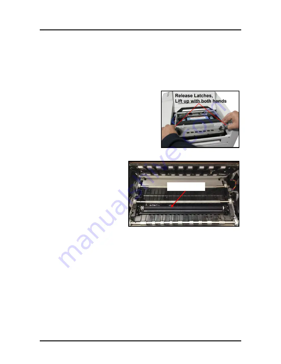
After the printer has finished performing
maintenance, carefully release the Latches and Open
the Clamshell.
3.
Open the Toolbox and press the “Wipe Printhead” button.
4.
The Wiper Roller will be presented
through the opening in the lower
section of the print engine. The
Service Station will cycle through
its normal wiping and capping
routine; providing you with the
opportunity to inspect the condition
of the Wiper Roller.
CAUTION
: Keep all loose items
and hands away from the moving
parts within the print engine. Do
NOT try to touch or clean the
moving components. Injury or
damage may result.
5.
Inspect the Wiper Roller for signs of damage/wear (fabric is fuzzy, torn, uneven) and debris
(fibers, hair, particle accumulation, etc…).
Contact your service support representative if you see signs of wear or debris on the roller. The
wiper roller may need to be cleaned or replaced.
NOTE
: A new (unused) Wiper Roller will be white. Once the roller has been used, for a short
period of time, it will turn black with ink. This is normal.
WARNING
: Without training and experience it can be difficult to identify a worn or dirty wiper
roller. When in doubt, the Wiper Roller should be replaced. Operating the printer with a worn or
dirty wiper roller can cause damage to the printhead. If the printhead is replaced it is also
recommended that the Wiper Roller be replaced at the same time.
6.
As soon as you are finished inspecting the Wiper Roller; carefully close and latch the Clamshell.
WARNING:
If you leave the Clamshell open too long this may cause nozzle dehydration.
Important!
Make sure to hold the latches open (unlocked position) until the clamshell is closed.
Then slowly release the latches. If this rule is not followed damage to the latch posts and or door
switch may result.
7.
Close the Top Cover.
Summary of Contents for AS-1180C
Page 75: ...SECTION 4 DISASSEMBLY AND ASSEMBLY 73 a J1002 Cable J1002 Socket Location Connection ...
Page 76: ...SECTION 4 DISASSEMBLY AND ASSEMBLY 74 b J1000 Cable J1000 Socket Location Connection ...
Page 77: ...SECTION 4 DISASSEMBLY AND ASSEMBLY 75 c J551 Cable J551 Socket Location Connection ...
Page 78: ...SECTION 4 DISASSEMBLY AND ASSEMBLY 76 d J703 Cable J703 Socket Location Connection ...
Page 79: ...SECTION 4 DISASSEMBLY AND ASSEMBLY 77 e P2002 Cable P2002 Socket Location Connection ...
Page 80: ...SECTION 4 DISASSEMBLY AND ASSEMBLY 78 f P2004 Cable P2004 Socket Location Connection ...
Page 81: ...SECTION 4 DISASSEMBLY AND ASSEMBLY 79 g P2006 Cable P2006 Socket Location Connection ...
Page 82: ...SECTION 4 DISASSEMBLY AND ASSEMBLY 80 h J35 Cable J35 Socket Location Connection ...
Page 83: ...SECTION 4 DISASSEMBLY AND ASSEMBLY 81 i P1 Cable P1 Socket Location Connection ...
Page 84: ...SECTION 4 DISASSEMBLY AND ASSEMBLY 82 j P2005 Cable P2005 Socket Location Connection ...
Page 85: ...SECTION 4 DISASSEMBLY AND ASSEMBLY 83 k P2003 Cable P2003 Socket Location Connection ...
Page 86: ...SECTION 4 DISASSEMBLY AND ASSEMBLY 84 l J20 Cable J20 Socket Location Connection ...
Page 87: ...SECTION 4 DISASSEMBLY AND ASSEMBLY 85 m J2001 Cable J2001 Socket Location Connection ...
Page 180: ......
Page 181: ...Copyright Neopost USA 2014 ...


