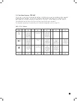
18
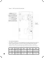
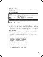
Diagram 18. Generic example
MIDAS
®
3-wire sinking output
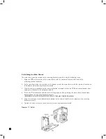
5.8 Refitting the Main Chassis
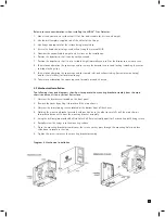
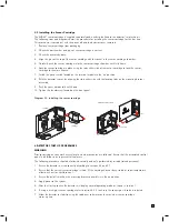
The main chassis can be refitted to the mounting bracket assembly using the following steps.
1. Align the PCB at the top rear of the main chassis with the connector located at the top of the
mounting bracket assembly
2. At the same time align the two tubes at the bottom rear of the main chassis with the two tubes located on
the bottom of the mounting bracket assembly.
3. Slide the chassis backwards on the mounting bracket assembly so that the PCB and connector and tubes
engage simultaneously. (See diagram below).
4. Ensure the PCB, connector and tubes are fully engaged by firmly pushing the main chassis horizontally
backwards on the mounting bracket assembly
(WARNING: DO NOT PUSH ON THE LCD AS THIS MAY CAUSE DAMAGE).
5. Align the two fixing screws located at the bottom of the chassis with the screw threads on the mounting
bracket assembly.
6. Tighten the screws to secure the chassis to the mounting bracket assembly.
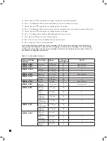
Diagram 19. Refitting the chassis.
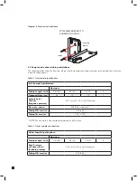
Diagram 19. Generic Example MIDAS
®
sourcing 4-20 mA with PoE power
Diagram 20. Generic example
MIDAS
®
isolated 4-20 mA
output with PoE power

