48
10.1 Fitting the Pyrolyzer Module
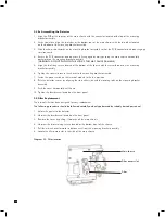
1. Isolate the power to the detector.
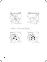
2. Unscrew the captive thumbscrew located on the front panel.
3. Remove the cover by pulling it forwards off the main chassis.
4. Unscrew the two captive screws located at the bottom front of the chassis.
5. Pull the main chassis forwards to disconnect it from the mounting bracket assembly.
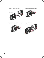
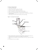
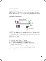
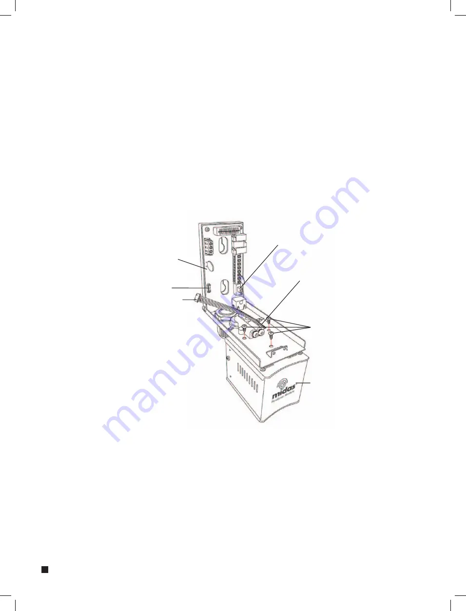
6. Thread the connector and ribbon cable from the pyrolyzer through the rectangular access in the bottom of
the mounting bracket.
7. Plug the connector into the socket (con5) at the bottom left of the terminal board.
Diagram 33. Connecting the Pyrolyzer module
8. Offer the pyrolyzer module up underneath the mounting bracket ensuring that the fitting at the top rear of
the pyrolyzer mates with the sample inlet port at the bottom of the mounting bracket.
9. Align the three screw mounting bosses on the top of the pyrolyzer with the three screw holes in the mounting
bracket.
10. Insert and tighten the three screws provided.
Rectangular access
at bottom of bracket
Mounting screws (x3)
Socket
Connector
Pyrolyzer module
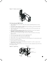
Power switch
Thermal
module

