49
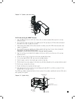
Gas sample
inlet as NF3
To MIDAS sample
inlet as HF
Pyrolyzer Option
super-heater
Gas sample
chamber
Needle valve
(Heater flow adjustment)
Diagram 34. Pyrolyzer main components
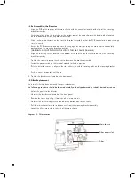
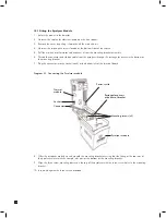
10.2 Re-Assembling the MIDAS
®
Detector
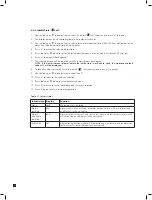
1. Align the PCB at the top rear of the main chassis with the connector located at the top of the mounting
bracket assembly.
2. At the same time align the two tubes at the bottom rear of the main chassis with the two tubes located on
the bottom of the mounting bracket assembly.
3. Slide the chassis backwards on the mounting bracket assembly so that the PCB and connector and tubes
engage simultaneously.
4. Ensure the PCB, connector and tubes are fully engaged by firmly pushing the main chassis horizontally
backwards on the mounting bracket assembly
(WARNING: DO NOT PUSH ON THE LCD AS THIS MAY CAUSE DAMAGE).
5. Align the two fixing screws located at the bottom of the chassis with the screw threads on the mounting
bracket assembly.
6. Tighten the screws to secure the chassis to the mounting bracket assembly.
7. Fit sensor cartridge MIDAS-S-HFX into the sensor cartridge chamber.
8. Switch the power switch on the terminal module to the ‘on’ position.
9. Refit the detector’s cover by aligning the slots either side with the locating tabs on the mounting bracket assembly.
10. Push the cover horizontally until home.
11. Tighten the thumbscrew located on the front panel.
12. After applying power ensure that the sensor cartridge gas id code 08-03 is set. Refer to section 8.2.2 for
details of how to set the gas id code.
The MIDAS
®
gas detector automatically detects the connection of the pyrolyzer module and provides all the power
and signaling for the device.
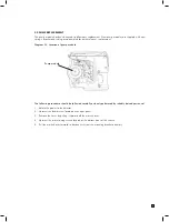
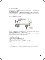
Diagram 35. Pyrolyzer detail
Gas sample
inlet as NF3
Exhaust Tubing
To MIDAS sample
inlet as HF
Jumper Teflon tubing
between pyrolyzer and
MIDAS (included with
pyrolyzer option)
Mounting holes
for M3 screws (3)
Terminal for Power
and communication
connection
Pyrolyzer Option
Freon filter

