51
11 ANALOG INPUT MODULE
MIDAS
®
can be fitted with an analog module (MIDAS-T-00A) that allows it to be used as a control ‘hub’ for other
remotely connected 4-22 mA analog detection devices such as other gas detectors, flow sensor cartridges and
other industrial monitoring apparatus.
NOTE:
Not all analog devices will be compatible with the MIDAS
®
Analog Input module. Zellweger Analytics
is not responsible for ensuring the compatibility of the MIDAS
®
transmitter and analog input module with other
manufacturers’ analog output devices. Please contact your local Zellweger Analytics representative prior to
ordering this option.
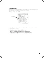
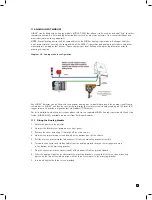
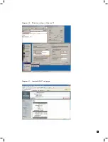
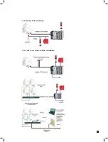
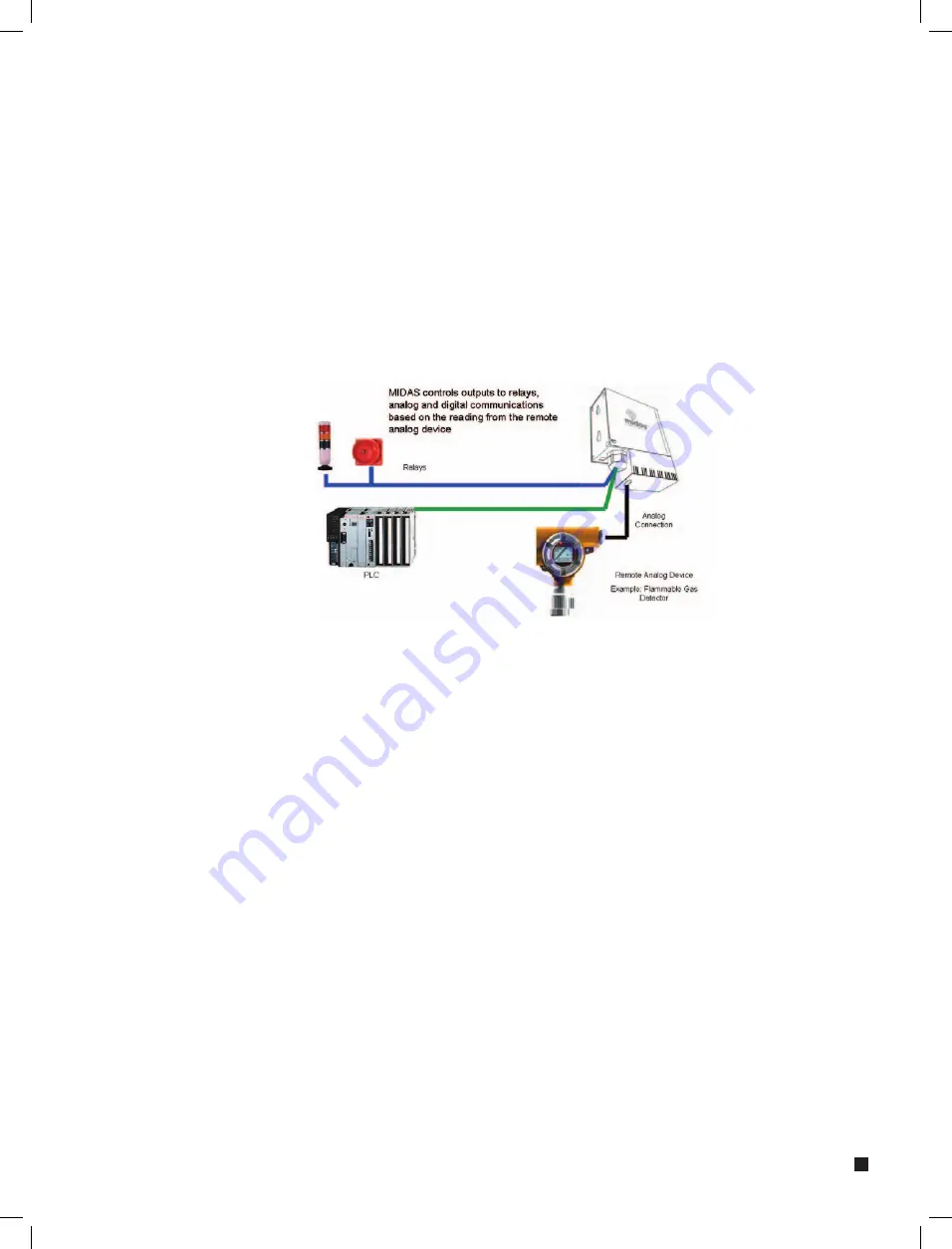
Diagram 38. Analog module configuration
Any MIDAS
®
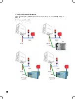
detector can be fitted with the optional analog input module that accepts the analog signal from a
remote device. MIDAS
®
can then be configured to display the remote system’s analog reading on the local LCD,
trigger relays and provide a digital output via Modbus/TCP Ethernet.
For full installation and wiring instructions please refer to the separate MIDAS
®
Analog Input module Quick Start
Guide (MIDAS-A-023) available on request from Zellweger Analytics.
11.1 Fitting the Analog Module
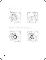
1. Isolate the power to the detector.
2. Unscrew the thumbscrew located on the front panel.
3. Remove the cover by pulling it forwards off the main chassis.
4. Unscrew the two retaining screws located at the bottom front of the chassis.
5. Pull the main chassis forwards to disconnect it from the mounting bracket assembly.
6. Thread the connector and ribbon cable from the analog module through the rectangular access
in the bottom of the mounting bracket.
7. Plug the connector into the socket (con5) at the bottom left of the terminal board.
8. Offer the analog module up underneath the mounting bracket ensuring that the three screw mounting
bosses on the top of the module align with the three screw holes in the mounting bracket.
9. Insert and tighten the three screws provided.


