24
MaxPac Dual/Triple-Screen 8230 XRA2/3-Series User Operation and Maintenance Guide
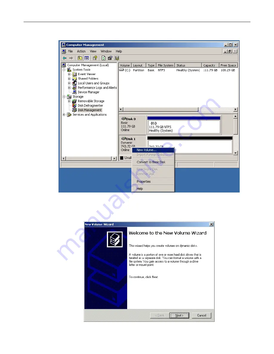
Figure 2-27. Select the New Volume option
23) Observe the
New Volume Wizard
appear as shown in Figure 2-28.
Figure 2-28. The New Volume Wizard
Page 1: ...User Operation and Maintenance Guide Operating and Maintaining Your MaxPac Dual Triple Screen 8230 XRA2 3 Series High Performance Transportable Workstation MaxVision Corporation 495 Production Avenue...
Page 2: ...er new or remanufactured In the event that the Product returned is not defective you will be responsible for freight costs for return shipment to you The foregoing warranty shall not apply to Product...
Page 3: ...nts relative to its subject matter It may be modified only by a writing executed by an authorized representative of MaxVision No MaxVision reseller or sales representative is authorized to make any mo...
Page 4: ...Array with Separate System Drive 17 Configuring the RAID Array with Hot Spare and System Partition on RAID Array 31 Chapter 3 Module Replacement and Upgrade Procedures 42 Introduction 43 Required Tool...
Page 5: ...ular System Maintenance 85 Cleaning Interior Dust 85 Replacing the Lithium Battery 85 Maintaining Cleaning the Baghdad Filters 85 Resetting the Motherboard BIOS 89 Appendix C Screws and Required Tools...
Page 6: ......
Page 7: ...MaxPac Dual Triple Screen 8230 XRA2 3 Series User Operation and Maintenance Guide 1 Chapter 1 Quick Start Setup...
Page 8: ...ddle means click the middle mouse button on the indicated item Click right means click the right mouse button on the indicated item Double click means click twice consecutively with the left mouse but...
Page 9: ...om the outside of the box and save it for later use as discussed below 2 Clear an area on a desk or table on which to place the MaxPac system Note In order to raise or lower the handle on the Pelican...
Page 10: ...aghdad Filters documentation packet and any special order cabling or other items 2 Check the packing slip to ensure that everything is as you expect with regard to the main system and the contents of...
Page 11: ...ready attached to the main chassis Present the front portion of the left hand filter assembly including its filter element to the rear portion of the assembly on the main chassis Use the flanges to en...
Page 12: ...Figure 1 11 Note You may hear a squeaking noise when you unfold the second screen This is caused by the polyurethane clutch and is part of the friction mechanism that holds the screen steady Do NOT a...
Page 13: ...stem 1 Place one hand underneath the system and the other hand on top of the system Figure 1 16 Press down lightly with the hand on top of the system while gently pulling the bottom of the system forw...
Page 14: ...he right hand side of the system Figure 1 20 Figure 1 20 Figure 1 21 3 The mouse may be plugged into the PS2 connector located next to the keyboard connector as shown in Figure 1 21 Alternatively you...
Page 15: ...he top of the system immediately behind the center display screen Figure 1 24 3 Due to extensive system initialization and verification checks the BIOS boot up process can take a significant amount of...
Page 16: ...ine in this context the term base refers to the bottom of the system when it is standing on the table as illustrated earlier in this manual Entering the name you wish to be associated with this system...
Page 17: ...they may be improperly ordered such that the mouse cursor leaps from screen to screen in a non intuitive way In such a case right mouse click on a blank area of an active screen desktop select the Pro...
Page 18: ...soon as possible After the 30 day grace period has expired the system won t even let you logon until you do register and activate the OS Shutting Down the System In order to shut the system down grace...
Page 19: ...MaxPac Dual Triple Screen 8230 XRA2 3 Series User Operation and Maintenance Guide 13 Chapter 2 Setting Up the Software Devices Network RAID Array...
Page 20: ...Color Quality Highest 32 bit Resolution 2 or 3 x 20 1 displays 1600 x 1200 Irrespective of the configuration the graphics on your system will have been custom pre configured to suite your particular r...
Page 21: ...ital and analog inputs These custom configurations will come equipped with a special documentation addendum that details the actions of the INPUT button in the case of standard configurations the sour...
Page 22: ...ttons on this control panel to access the Picture in Picture dialog Figure 2 5 Figure 2 5 Figure 2 6 3 Use this dialog to turn the Picture and Picture window On Off and to specify characteristics such...
Page 23: ...r three disks are used to implement the RAID data array Figure 2 7 Figure 2 8 Installing the Web Based 3ware Software If you reload your operating system then you will also need to reload the appropri...
Page 24: ...BIOS Manager Figure 2 10 press and hold the ALT alternate key and while still holding this key press the number 3 key This will invoke the 3ware BIOS manager in most cases you will be presented with...
Page 25: ...2 14 5 Use the up down arrow keys to highlight the RAID 5 option and then press the Enter key to select this option Figure 2 14 Figure 2 15 6 Use the up down arrow keys to highlight the Stripe Size it...
Page 26: ...re 2 18 and then press the Enter key to save your changes Figure 2 18 Figure 2 19 13 You will be presented with a warning dialog as shown in Figure 2 19 Press the Y yes to allow the write cache to be...
Page 27: ...the boot process you will see the BIOS report the existence of your new RAID array 17 Once the system has booted up into Windows right click on the My Computer icon and then select the Manage option...
Page 28: ...shown in Figure 2 24 20 Click the Next button to be presented with the Completing the Wizard screen as shown in Figure 2 25 and then click the Finish button to perform the operations and exit the wiza...
Page 29: ...ed to form the RAID array were each 400 GB in size Observe in Figure 2 26 that Disk 1 is shown as being approximately 800 GB in size where 800 GB equates to 2 3 of the 3 x 400 GB capacity of the data...
Page 30: ...al Triple Screen 8230 XRA2 3 Series User Operation and Maintenance Guide Figure 2 27 Select the New Volume option 23 Observe the New Volume Wizard appear as shown in Figure 2 28 Figure 2 28 The New Vo...
Page 31: ...r presented by the system or enter a different letter if you require as shown in Figure 2 31 Figure 2 31 Figure 2 32 27 Click the Next button to be presented with the Format Volume screen Click the Fo...
Page 32: ...26 MaxPac Dual Triple Screen 8230 XRA2 3 Series User Operation and Maintenance Guide Figure 2 33 The Completing the Wizard dialog Figure 2 34 Disk 1 is now shown as being Dynamic Online and Healthy...
Page 33: ...some stage one of the disks in the array may start to degrade or go completely off line For the purposes of these discussions we are going to power down the system physically remove Disk 01 from the a...
Page 34: ...was previously part of a 3ware RAID array the system may report that the new disk is INOPERABLE as illustrated in Figure 2 39 Alternatively the system may report the new disk as being AVAILABLE as ill...
Page 35: ...MaxPac Dual Triple Screen 8230 XRA2 3 Series User Operation and Maintenance Guide 29 Figure 2 39 Figure 2 40...
Page 36: ...30 MaxPac Dual Triple Screen 8230 XRA2 3 Series User Operation and Maintenance Guide Figure 2 41 Figure 2 42...
Page 37: ...reflect system configurations that have the system partition established on the RAID array itself leaving a hot spare drive as illustrated in Figure 2 44 Configurations with a separate system drive ar...
Page 38: ...blishing a system from the ground up and that you have four new disks in your disk caddy 1 Start to power up the system When you see the BIOS message Alt 3 to access 3ware BIOS Manager Figure 2 45 pre...
Page 39: ...s to highlight the RAID Configuration item and then press the Enter key to access an associated pop up dialog Figure 2 49 6 Now use the up down keys to highlight the RAID 5 option and then press the E...
Page 40: ...ss the Y yes key to allow the write cache to be enabled note that this mode significantly improves performance but it can result in a loss of data in the event of a power failure so MaxVision STRONGLY...
Page 41: ...VD you ve created yourself as discussed in Appendix A and if that CD DVD or the first CD DVD in a set has the Acronis Bootable Rescue Media software on it then simply insert this disk in the drive and...
Page 42: ...with a message saying that this is not the last created volume in the archive and requesting you to insert the last created volume In this case replace the current CD DVD with the last disk from the s...
Page 43: ...ition Size page Figure 2 64 29 We have chosen to establish a 200 GB system partition in this example the remaining Free Space will automatically be allocated to the data portion of the RAID 5 array Cl...
Page 44: ...ws Note Once you have re loaded the original MaxVision supplied image you will also have to re run the initialization procedures including re activating re registering your OS license as described ear...
Page 45: ...MaxPac Dual Triple Screen 8230 XRA2 3 Series User Operation and Maintenance Guide 39 Figure 2 69 Figure 2 70 Figure 2 71...
Page 46: ...m the array thereby simulating a catastrophic failure on this disk and power up the system back up again 1 Power down the system and remove the center data disk Disk 01 as shown in Figure 2 73 2 Power...
Page 47: ...drive you ve just added to the system Use the up down arrow keys to highlight the uncommitted drive and press the Enter key to select it the fact this has been selected will be indicated with an aste...
Page 48: ...42 MaxPac Dual Triple Screen 8230 XRA2 3 Series User Operation and Maintenance Guide Chapter 3 Module Replacement and Upgrade Procedures...
Page 49: ...acing any parts it is strongly recommended to have a plastic container divided into small compartments and to label these compartments as you work Required Tools and Techniques Most of the module repl...
Page 50: ...e 3 1 Figure 3 2 3 Gently lift the left hand screen s monitor cable access panel away from the system Figure 3 2 4 Unscrew the jack screws holding the DVI data cable connector Figure 3 3 and gently pu...
Page 51: ...le Right Hand Screen 1 Lay the system flat on the table with the displays in the closed position and facing upwards it is recommended that you lay the system on bubble wrap in order to protect the fin...
Page 52: ...river to remove the eight 6 32 1 4 black countersunk screws four on each site holding the screen to its hinge bar similar to the procedure for the left hand screen as shown in Figure 3 6 and then lift...
Page 53: ...o a vertical position standing against the cable side pair of wing brackets as illustrated in Figures 3 15 and 3 16 as these monitors are expensive items it is strongly recommended that you keep hold...
Page 54: ...16 black countersunk screws holding the center screen s monitor cable access panel Figure 3 18 6 Gently lift the center screen s monitor cable access panel away from the system Figure 3 19 Figure 3 19...
Page 55: ...ing the cable access cover for the center screen observe that the cables exit the screen assembly through the larger upper cable guide as shown in Figure 3 23 When re installing the center screen once...
Page 56: ...Figure 3 27 2 Use a Phillips 2 screwdriver to remove the two 10 32 1 4 black countersunk screws holding the screen assembly to the chassis there is one on each side on the top side of the system close...
Page 57: ...spring mechanism expands them back into their locked position 8 Return to facing the top of the system and use a Phillips 2 screwdriver to remove the five 6 32 1 4 black countersunk screws three on t...
Page 58: ...ion support Note The BIOS will always report the true amount of physical memory that is present in the system This may be as much as 12 GB However the actual amount of memory that can be seen by the s...
Page 59: ...g an existing PCI card use a Phillips 2 screwdriver to remove the 6 32 screw attaching the card s retaining bracket to the inner chassis as shown in Figure 3 36 If you are adding a new card remove the...
Page 60: ...PCI Express Card Secondary card for third screen and Projector Port In the case of a dual screen MaxPac system the graphics for both screens will be handled by a single PCI Express card as discussed...
Page 61: ...card The foam attached to the hinged inner lid of the MaxPac will hold pressure to the back of the card when properly secured PCI Express Card Primary In the case of a dual screen MaxPac system the g...
Page 62: ...re that the tongue on the new replacement card s faceplate lines up with the slot in the chassis you may have to bend the tongue slightly in the case of a new card Note When removing the video cables...
Page 63: ...ctor from the auxiliary power distribution board Figure 3 49 Figure 3 49 Figure 3 50 3 Unplug the bottom power input connector from the auxiliary power distribution board as illustrated in Figure 3 50...
Page 64: ...e new auxiliary power distribution assembly supplied by MaxVision support and incorporate it into the system by performing the steps described above in reverse order Main Power Distribution Board Note...
Page 65: ...e 3 58 Figure 3 58 Figure 3 59 3 In order to replace an individual drive turn each of the four knurled screws attached to the upper binding bar until they pop out and then remove the upper binding bar...
Page 66: ...h MaxPac especially when you are actually replacing individual disks Optical Drive CD DVD 1 Note that it is not necessary to open the display assembly into its service position in order to perform thi...
Page 67: ...release the latch with your finger or thumb nail while pulling ion the cable 5 Remove the CD Audio cable as illustrated in Figure 3 65 6 Use a Philips 1 screwdriver to remove the two screws attaching...
Page 68: ...earlier in this chapter 2 Disconnect the external cooling fan assembly s power supply cable from the main distribution board The connector is shown as being pointed to by a screwdriver in Figure 3 68...
Page 69: ...e of the cooling fan assembly Use a Phillips 2 screwdriver to loosen these captured screws Figures 3 72 and 3 73 Figure 3 72 Figure 3 73 3 Gently lift the cooling fan assembly away from the chassis as...
Page 70: ...eed to replace the entire power supply as discussed below 1 Open the display assembly into its service position as discussed earlier in this chapter 2 Remove the video distribution board as discussed...
Page 71: ...gently remove the protector plate to expose the wire harness Figure 3 83 Figure 3 82 Figure 3 83 6 Disconnect the power connector to the main distribution board make sure to use the connector s relea...
Page 72: ...l It is easy to damage the motherboard unless one has the appropriate tools and training For this reason you must either return the MaxPac system to MaxVision or be factory trained by MaxVision person...
Page 73: ...between the hard disk cage the CPU heatsink fan assembly and the power distribution board as shown in figure 3 92 Figure 3 92 Figure 3 93 6 The soft power cable must be removed from the motherboard co...
Page 74: ...ll need a second person to hold the monitor assembly while you lift the inner chassis out of the outer chassis Figure 3 98 Note As the weight of the inner chassis is removed the display assembly and o...
Page 75: ...Each fan has its own power connector that is attached to the main motherboard Disconnect the power connector associated with the CPU fan Figure 3 103 14 Figures 3 104 and 3 105 illustrate the removal...
Page 76: ...ce Guide Figure 3 106 Figure 3 107 Figure 3 108 Figure 3 109 16 Remove the screws from the bottom of the shadow box as shown in Figure 3 109 then carefully remove the shadow box fan power and speaker...
Page 77: ...dy of the connector Figures 3 113 18 Disconnect the ATX 24 pin power connector from the motherboard Pull the connector up while using a flat blade screwdriver to push the top of the release catch faci...
Page 78: ...ure 3 119 22 The soft power cable must be removed from the motherboard connection posts the location of this connector is pointed out in Figure 3 119 Observe that this cable connector is attached to t...
Page 79: ...otherboard out and place on a protected surface as shown in Figures 3 124 and 3 125 Figure 3 124 Figure 3 125 26 Under the direction of MaxVision support carefully remove the XEON series 5100 CPU from...
Page 80: ...the suspect or bad motherboard before any additional handling of either motherboard The installation of one of the pin protectors is illustrated in Figures 3 129 3 130 and 3 131 Figure 3 130 Figure 3...
Page 81: ...ally depress the locking lever shown in its raised unlocked position in Figures 3 129 and 3 130 into its lowered locked position as illustrated in Figure 3 131 28 Gently attach the XEON CPUs into the...
Page 82: ...te If you do re load the original MaxVision supplied image you will also have to re run the initialization procedures including re activating re registering your OS license as described earlier in thi...
Page 83: ...use to select the Acronis item as shown in Figure A 1 5 Following the splash screen Figure A 2 under the Pick a Task heading select the Backup option the top item as illustrated in Figure A 3 Figure A...
Page 84: ...78 MaxPac Dual Triple Screen 8230 XRA2 3 Series User Operation and Maintenance Guide Figure A 7 Figure A 8 Figure A 9 Figure A 10 Figure A 11 Figure A 12...
Page 85: ...MaxPac Dual Triple Screen 8230 XRA2 3 Series User Operation and Maintenance Guide 79 Figure A 13 Figure A 14 Figure A 15 Figure A 16 Figure A 17 Figure A 18...
Page 86: ...vation before use no 30 day grace period At this time you will need to supply the correct OS license number for the MaxPac and activate prior to use this procedure may vary depending on the version an...
Page 87: ...MaxPac Dual Triple Screen 8230 XRA2 3 Series User Operation and Maintenance Guide 81 Figure A 21 Figure A 22 Figure A 23 Figure A 24 Figure A 25 Figure A 26...
Page 88: ...82 MaxPac Dual Triple Screen 8230 XRA2 3 Series User Operation and Maintenance Guide Figure A 27 Figure A 28 Figure A 29 Figure A 30 Figure A 31 Figure A 32...
Page 89: ...MaxPac Dual Triple Screen 8230 XRA2 3 Series User Operation and Maintenance Guide 83 Figure A 33 Figure A 34 Figure A 35 Figure A 36 Figure A 37 Figure A 38...
Page 90: ...84 MaxPac Dual Triple Screen 8230 XRA2 3 Series User Operation and Maintenance Guide Figure A 39 Figure A 40...
Page 91: ...sages grills and heat sinks Close up the system Replacing the Lithium Battery A Lithium Ion battery is included with the system motherboard This battery is used for the Real Time Clock circuit The exp...
Page 92: ...of thumb is when the filters look physically dirty The following discussions are based on the left hand filter The same actions apply to the right hand filter It is more efficient to clean both filte...
Page 93: ...228 0002 0 comprises a pump spray cleaner and an aerosol spray containing replacement oil Figure B 8 Place the filter element on a working surface that is protected by some form of absorbent disposabl...
Page 94: ...that the cotton in the filter element will absorb and distribute the oil into an even film thus it is important to use only a single pass for each area of the filter and to not over spray the filter N...
Page 95: ...discharge a major power surge or user error you may reset the BIOS as follows 1 Power the system down completely a simple Start Turn Off Computer Restart command is typically NOT recommended or suffic...
Page 96: ...arrow keys to highlight the Load Optimal Defaults item Figure B 2 4 Press the Enter key to select this item You will be presented with a confirmation screen as shown in Figure B 3 Figure B 3 Figure B...
Page 97: ...n and Maintenance Guide 91 Appendix C Screws and Required Tools Screws The various screws used in a MaxPac 8230 Series X Class system are illustrated approximately full size as shown in Figure C 1 Fig...
Page 98: ...y stroking the blade with a permanent magnet Using a high quality universal screwdriver with replaceable Phillips 1 and 2 bits is a good idea to ensure that your bits are always in excellent condition...
Page 99: ...vision com or the technical support and customer service hotline 800 533 5805 If MaxVision s technical support determines that the product is defective MaxVision will issue a Return Material Authoriza...