


86
1
1921 Slauson
A
ve. Santa Fe Springs, CA. 90670 (800) 227-41
16 F
AX (888) 771-7713
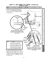
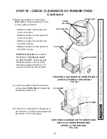
STEP 18 - CHECK CLEARANCE OF RUNNER PADS -
Continued
7.
Ensure the bottom tandem rollers are
seated against inner column
(FIG.
86-1)
. Next, slide the bottom pad
down against wedge until there is no
clearance between inner column and
bottom pad
(FIG. 86-1)
. Then, back
off (slide up) bottom pad by 1 hole
position to create clearance between
pad and inner column.
BOTTOM
PAD
LH
RUNNER
BOTTOM
TANDEM
ROLLERS
WEDGE
INNER
COLUMN
ADJUSTING LOWER PAD
FIG. 86-1
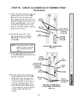
8.
Bolt bottom pad to LH runner
with 2 bolts and 2 lock washers
(FIG. 86-2)
. Torque the 2 bolts
to
9-14 lb-ft
.
BOLTING LOWER PAD &
ADJUSTING UPPER PAD
FIG. 86-2
UPPER
PAD
LH
RUNNER
WEDGE
INNER
COLUMN
UPPER
TANDEM
ROLLERS
BOLT &
LOCK WASHER
(2 PLACES)
BOLT HOLES
TO ADJUST PAD
POSITION
(8 PLACES)
BOLT HOLES
TO ADJUST PAD
POSITION
(8 PLACES)
9.
Unbolt upper spacer pad from LH
runner
(FIG. 86-2)
. Keep bolts & lock
washers to reinstall.
NOTE:
Keep spacer pad in place
between column & runner
after unbolting pad from
runner.
10.
Ensure upper tandem rollers are
seated against inner column
(FIG.
86-2)
. Next, slide the upper pad
up against wedge until there is no
clearance between inner column
and upper pad
(FIG. 86-1)
. Then,
back off (slide down) lower pad by
1 hole position to create clearance
between upper pad and inner
column.
BOTTOM
PAD
Summary of Contents for BMR-CS
Page 103: ......