Page 60 P/N 03521015 Rev U1
Bio-Medical Devices Intl
17171 Daimler Street Irvine, CA 92614 800-443-3842 www.maxair-systems.com
14. Helmet
All three CAPR Helmets (Section 3.6) are shipped with the 2051-07 (01031269) Cage in place to protect the motor-blower
assembly:
● 2081-03: 01031001 Helmet, 2071-01 (03531021) Liner, 2051-07 (01031269) Cage, 2590-05 Power Cord
● 2082-03: 01031001 Helmet, 2071-02 (03531104) ChinBar Liner, 2051-07 (01031269) Cage, 2590-05 Power Cord
● 2083-03: 01031001 Helmet, 2071-03 (03531148) Hard Hat Liner, 2051-07 (01031269) Cage, 2590-05 Power Cord
Prepping the Helmet for Storage
1. Clean all dirty surfaces per
Section 23.
2. Assemble a Filter Cartridge, Section 12, or the
SnapOn Cage, reverse of steps 1-3 directly above,
Prepping the Helmet for use.
3. Follow storage instructions
per Section 28.
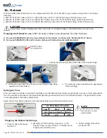
SnapOn Cage
(O.N. 2051-07)
1. Unsnap the left and right side Snap Tabs of the SnapOn Cage.
2. Unsnap the rear Snap Tab and remove the SnapOn Cage lifting
upward and off the Helmet.
3. The helmet is ready to assemble the appropriate
Filter Cartridge.
Air Flow Switch Position
Low
Med
High
Air Flow in Liters Per Minute
190
215
240
NOTE
The flow levels, in liters
per minute, are only
approximate.
Setting Air Flow
When the Helmet is initially connected to the Battery, all LED Safety Status Indicators light briefly, then the red and yellow LEDs
turn off, and airflow increases to the appropriate operating level based on the Air Flow Switch position. The green LEDs will be
on as appropriate to the battery charge level.
Adjust the Air Flow Switch relative to the expected activity level and desired comfort level.
Prepping the Helmet for use
(2081-03 shown, follow same procedure for other Helmets)
A. For use with MAXAIR Hoods, the Cage remains on the Helmet - Continue with “Setting Air Flow” below.
B. For use with MAXAIR Cuffs and Shrouds continue with instructions immediately below.
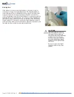
CAUTION
Always place a Filter Cartridge and Filter Cover Cap, or a SnapOn Cage on the Helmet when it is not in use.


