Page 50 P/N 03521015 Rev U1
Bio-Medical Devices Intl
17171 Daimler Street Irvine, CA 92614 800-443-3842 www.maxair-systems.com
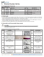
Cap of FCC
Air Inlet
Channel
(Cap
overhangs the
skirt
Skirt of FCC
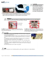
1. Start taping approximately one inch away
from the front-center of the Helmet. (One
inch to the side of the front Alignment post.
2. Tape over the Air Inlet Channel all
the way around the Filter Cover
Cap (FCC).
3. Cut the tape so that it stops
in the front-center of the
Helmet. This leaves about a
one inch open gap.
CAUTION
Ensure the Power Cord is disconnected
from the Battery before performing step 9.
9. Remove the tape
covering the air inlet
channel of the Filter
Cover Cap.
This concludes the test.
9.6 Warning Device: Yellow LED Air Flow Indicator Check - Tape Method
CAUTION
Prior to donning the system, the Safety Status Yellow LED function can and should be checked prior to use.
The yellow LED indicates that the respirator is no longer able to maintain adequate airflow for protection of the user
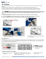
4. Pull back a tape flap about one inch
from the front-center of the Helmet,
leaving about a two inch open gap.
6. Allow the Helmet to stabilize
for about a minute. Notice
that the Yellow LED stays off.
7. Lay the tape flap back down to
reduce the gap back to a one
inch opening. Allow the Helmet to
stabilize for about a minute. Notice
the Yellow LED turns on.
5. Connect the Helmet Power Cord to the
Battery. Push the Power Cord Connector
into the Battery Receptacle until the Secure
Connection audibly clicks.
8. Disconnect the Helmet Power Cord from the
Battery - push the Secure Connection Button
down, pull Cord Connector out, release the
Button.


