


5-33
n111
: Slip Compensation Gain
Factory setting: 0.0
Range: 0.0 to 2.5
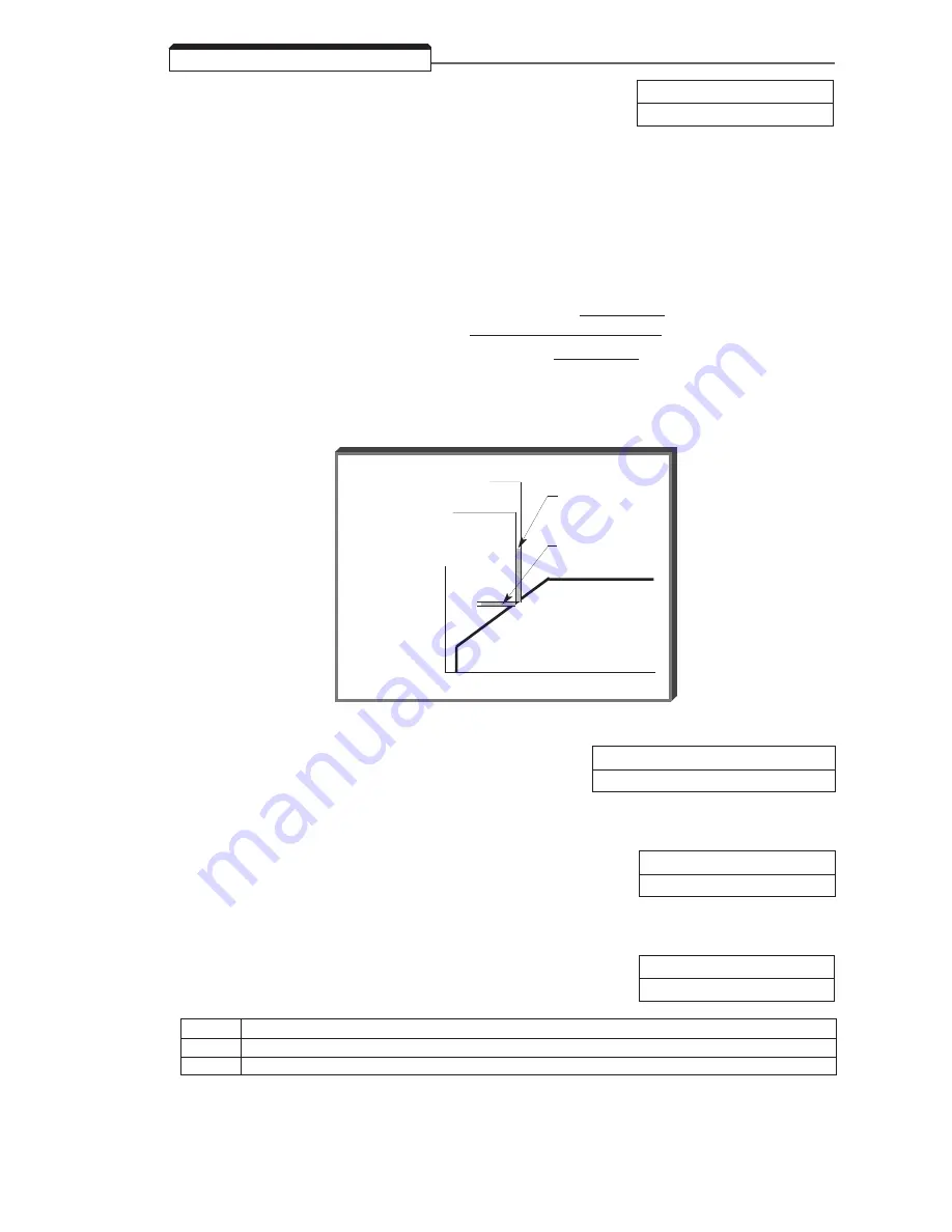
Slip compensation is used to increase motor speed to account for slip; the drive accomplishes this
by automatically boosting output frequency, with a corresponding boost in output voltage.
The slip compensation gain (n111) determines how much compensation frequency is added. If using
the GPD Drive in Open Loop Vector, typically no adjustment is necessary. The equation below
illustrates how the compensation frequency is generated.
NOTE: A slip compensation gain setting of 0.0 disables slip compensation.
(n110 * n036)
Compensation Frequency =
Output Current –
100
* n106 * n111
n036 – (n110 * n036)
100
Slip Compensation Equation
5.22 SLIP COMPENSATION
V
f
46.35 Hz actual output
1.35 H
frequency boost
corresponding
voltage boost
45 Hz command
n110
: Motor No-Load Current
Factory setting: See Table A3-1
Range: 0 to 99%
Motor no-load current (n110 ) is set as a percentage of motor full-load current (n036 ). It is used as
shown in the slip compensation equation.
n112
: Slip Compensation Primary Delay
Factory setting: 2.0 sec.
Time Constant
Range: 0.0 to 25.5 sec.
Parameter n112 can be increased to improve stability or decreased to improve response to load
changes.
n113
: Slip Compensation Selection
Factory setting: 0
During Regen
Range: 0 or 1
Setting
Description
0
Disabled - No slip compensation will be added when regenerating
1
Enabled - Slip compensation will be added when regenerating
Summary of Contents for GPD 315
Page 1: ...GPD 315 Technical Manual Magne Tek ...
Page 20: ...1 14 ...
Page 32: ...3 2 ...
Page 76: ...5 40 PID Block Diagram ...
Page 80: ...5 44 ...
Page 96: ...A1 8 ...
Page 100: ...A3 2 ...
Page 102: ...A4 2 ...
Page 110: ...A6 6 ...
Page 114: ......
Page 116: ......


