LSIS XGL-C22A User Manual Download Page 133


Chapter 7 XGT Dedicated Communication 


7-31 


7.4 Remote connection   


7.4.1 Summary of remote connection 


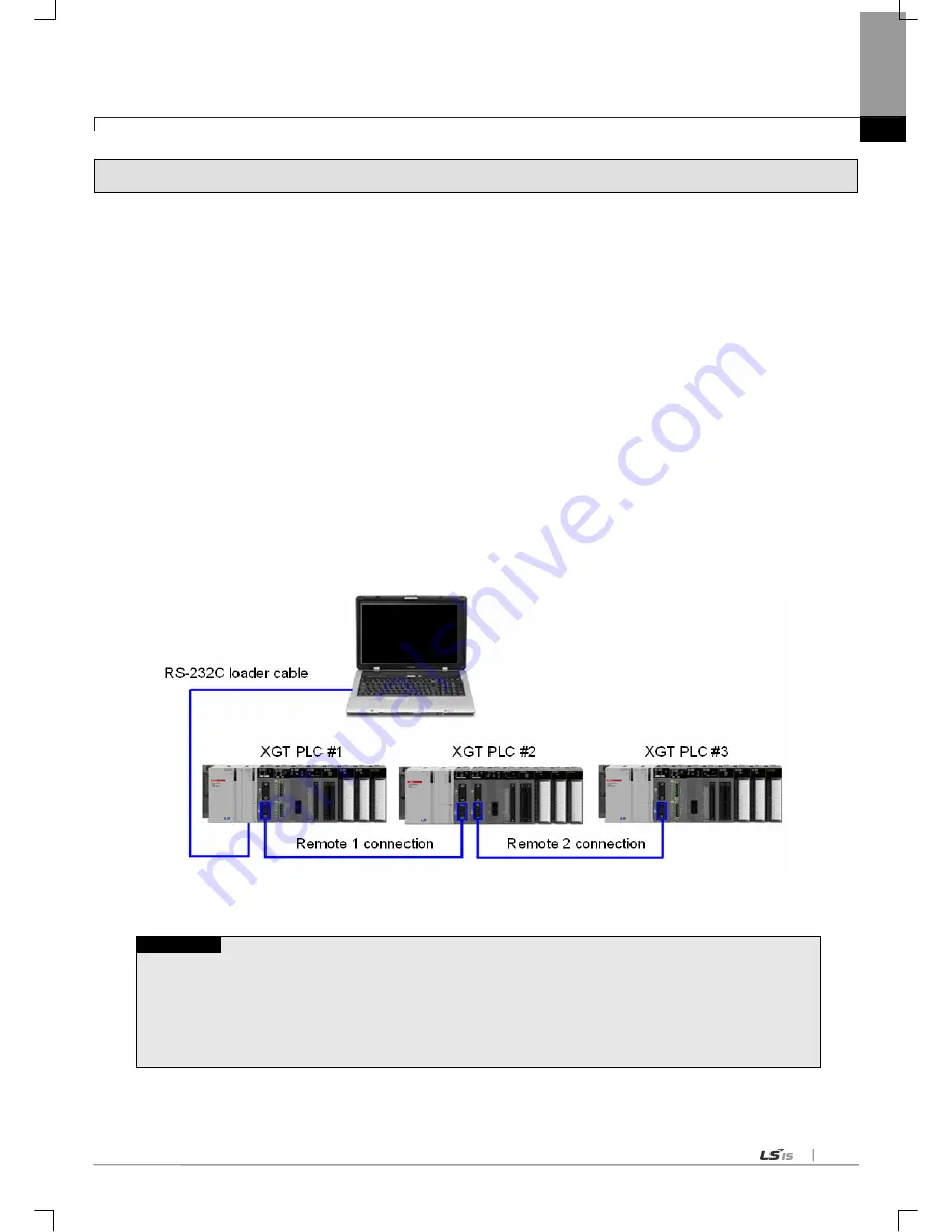
If XG5000 executed PC is located far from XGT-PLC, remote PLC program can be controlled for download, upload, 

debugging, monitoring, etc. through remote connection function of Cnet I/F module. Especially in case that XG5000 is located 

far away from PLC, PLC CPU can be conveniently accessible through remote function of XG5000. The remote connection 

via Cnet module is available for both 2 cases of remote connection between Cnet modules where XG5000 and PLC are 

directly connected via RS-232C and modem connection between XG5000 and PLC. For information about remote 

connection through modem, refer to the Ch.7.5. 


7.4.2 Limit of remote connection between Cnet I/F modules 

Limit of remote connection between Cnet I/F modules is as follows. 
 

(1) Communication type should be set as RS-232C, RS-422

note1)

(2) In case of remote connection, maximum supported remote connection stage is two. 
(3) Standard setting of Cnet I/F modules should be same for remote connection. 

         (4) In case of XGR, remote connection is available when station number of extension drive module is set within 1~15. 


[Figure 7.4.1] Remote connection between Cnet I/F modules 


Note 


Note1) Remote connection during communication between XGT Cnet I/F modules is supported when O/S version of 
XGT Cnet I/F module is 2.5 or above. Features are as follows.   
  (1) For communication type, only RS-232C, RS-422 method is supported. In case of remote connection using   

RS-485, remote connection is only available when the P2P link on the online menu of XG5000 is disabled. 

  (2) Remote connection is supported regardless of active mode. 

(3) Remote connection during communication is affected according to TRX period and an amount of data 

- In case TRX period is short or amount of data is huge, disconnection may occur. 

XG5000 

Summary of Contents for XGL-C22A

Page 1: ...sing us for your partner Programmable Logic Controller Cnet I F Module User s Manual Read this manual carefully before installing wiring operating servicing or inspecting this equipment Keep this manual within easy reach for quick reference XGL CH2A XGL C22A XGL C24A XGT Series http eng lsis biz ...

Page 2: ...me applicable instruction is violated This symbol indicates the possibility of severe or slight injury and property damages if some applicable instruction is violated Moreover even classified events under its caution category may develop into serious accidents relying on situations Therefore we strongly advise users to observe all precautions properly just like warnings The marks displayed on the ...

Page 3: ...ut signals are designed to be turned off and stopped for safety However there are cases when output signals remain active due to device failures in Relay and TR which can t be detected Thus you are recommended to install an addition circuit to monitor the output status for those critical outputs which may cause significant problems Never overload more than rated current of output module nor allow ...

Page 4: ... PLC power is off If not electric shock or damage on the product may be caused Be sure that every module is securely attached after adding a module or an extension connector If the product is installed loosely or incorrectly abnormal operation error or dropping may be caused In addition contact failures under poor cable installation will be causing malfunctions as well Be sure that screws get tigh...

Page 5: ...ns Secure terminal screws tightly applying with specified torque If the screws get loose short circuit fire or abnormal operation may be caused Securing screws too tightly will cause damages to the module or malfunctions short circuit and dropping Be sure to earth to the ground using Class 3 wires for FG terminals which is exclusively used for PLC If the terminals not grounded correctly abnormal o...

Page 6: ...nstalling or disassembling the module let all the external power off including PLC power If not electric shock or abnormal operation may occur Keep any wireless equipment such as walkie talkie or cell phones at least 30cm away from PLC If not abnormal operation may be caused When making a modification on programs or using run to modify functions under PLC operations read and comprehend all content...

Page 7: ...Safety Instructions Safety Instructions for waste disposal Product or battery waste shall be processed as industrial waste The waste may discharge toxic materials or explode itself Caution ...

Page 8: ...ransmission Standard 8 Menu bar and shortcut of XG PD 9 Operation Start 10 Diagnosis Function of XG PD Ch 7 XGT Dedicated Communication 11 Summary of Protocol 12 Frame Structure 13 XGT Communication Function 14 Remote Connection 15 Modem Communication 16 Communication Command Ch 8 Modbus Communication 17 General 18 Modbus Protocol 19 Structure of Frame 20 Modbus Server 21 Modbus RTU ASCII Client 2...

Page 9: ...2 3 2 4 2 5 3 2 3 4 4 5 5 1 5 6 5 7 5 8 6 20 6 24 V2 2 08 07 1 Head office address change Back cover 2 Adding contents 1 How to configure XGR basic system 4 8 2 Available device area per CPU 4 12 3 Fixing the contents 1 Introduction 1 1 1 3 2 Product Specification 2 3 3 Installation and Test Operation 4 4 4 9 4 Communication Parameter 6 1 6 47 5 XGT dedicated communication 7 3 7 5 6 Modbus communi...

Page 10: ...ble system configuration 5 add parity bit Ignore function 6 Change delay time setting typographical error 7 Change direct variable write typographical error 8 Change Modbus RTU typographical error 9 add UDATA instruction description 10 Add example UDATA function Entire CH1 3 2 CH2 2 CH4 5 1 CH3 4 2 CH5 2 1 CH6 1 1 CH6 2 1 CH6 1 1 CH7 2 3 CH8 CH9 5 CH10 6 V2 7 14 04 19 Change system configuration E...

Page 11: ...l User s manual for programming to explain how to use instructions that are used PLC system with XGK XGB CPU XGI XGR Instructions Programming User s Manual User s manual for programming to explain how to use instructions that are used PLC system with XGI XGR CPU XGK CPU User s Manual XGK CPUU CPUH CPUA CPUS CPUE XGK CPUU CPUH CPUA CPUS CPUE user manual describing about XGK CPU module power module ...

Page 12: ...nce 2 5 Chapter 3 Performance Specifications 3 1 Operation Mode Setting 3 1 3 2 Channel Operation during Normal Run 3 2 3 3 Channel Operation in Diagnosis Mode Loop Back 3 3 3 4 Method of Serial Interface 3 3 3 4 1 RS 232C interface 3 3 3 4 2 RS 422 485 interface 3 5 Chapter 4 Installation and Test Operation 4 1 Installation Environment 4 1 4 2 Precautions for Handling 4 2 4 3 Operation Sequence 4...

Page 13: ...r 6 3 6 2 Transmission Standard 6 4 6 2 1 Setting item 6 4 6 3 Installation and Execution of Software 6 6 6 3 1 XG5000 installation 6 6 6 3 2 USB device driver installation 6 10 6 3 3 Confirmation of installed USB device driver 6 13 6 4 Communication Module Registration 6 20 6 4 1 Off line registration of Cnet I F module 6 20 6 4 2 Online registration of Cnet I F module 6 21 6 4 3 How to read the ...

Page 14: ...5 7 5 2 Remote connection through modem 7 35 7 5 3 Communication procedure between PLC and dial up modem 7 39 7 6 Communication command 7 40 7 6 1 XGK command 7 40 7 6 2 XGI command 7 45 Chapter 8 Modbus Communication 8 1 General 8 1 8 1 1 Procedure of Modbus communication 8 1 8 2 Modbus Protocol 8 1 8 2 1 Kind of modbus protocol 8 1 8 2 2 Structure of modbus protocol 8 2 8 3 Structure of Frame 8 ...

Page 15: ... 2 3 Checking the operation 10 14 10 3 Modbus Communication 10 15 10 3 1 Settings when acting as Modbus RTU server 10 16 10 3 2 Setting when acting as RTU client 10 18 10 4 User defined Communication 10 24 10 4 1 Communication with other producer s product 10 24 10 4 2 Using P2P flag as conditional flag 10 30 10 5 Communication between HMI and inverter through Cnet I F module 10 35 10 6 SMS transm...

Page 16: ...List A 7 A 2 1 Special Relays List F A 7 A 2 2 Communication Relays List L A 15 A 2 3 LinkDevicesList N A 17 A 3 RS 232C interface through VisualBasic A 19 A 3 1 System configuration A 19 A 3 2 Pin No A 19 A 3 3 Mode setting A 20 A 3 4 Instruction A 20 A 3 5 Project A 21 A 3 6 Form design A 21 A 3 7 Make form procedure code A 22 A 3 8 Execute program A 28 A 3 Dimension A 19 ...

Page 17: ...C and computer etc and the function of modem communication to control remote PLC When programming refer to the following user manual XG5000 manual XGK instruction XGK manual XGI XGR instruction XGI instruction XGI manual XGR manual When configuring the system of the XGT Cnet I F module be careful of the followings XG5000 more than V4 0 XGT Cnet I F module OS more than V2 3 Note 1 This manual is wr...

Page 18: ...e PLC can be controlled by XG5000 connection dedicated communication and user defined communication 8 Various communication speeds can be set RS 232C 300bps 115 200bps RS 422 300bps 115 200bps 9 1 1 1 N N M communication if RS 422 channel used is available 10 Communication types of full duplex RS 422 RS 232C and half duplex RS 485 are supported 11 With satisfactory self diagnosis function and Loop...

Page 19: ...of communication module if possible mount the communication module in the basic base The following table indicates the available service type according to CPU Apply it when configuring the system Classification XGK XGI XGR CPUH CPUU CPUA CPUS CPUE CPUU CPUH CPUS CPUH T CPUH F Max no of module using high speed link Not used Max no of module using P2P 8 EA Max no of module using dedicated service 24...

Page 20: ...ort XGL C42A RS 422 2 ports Note 1 The above program can be downloaded from our website now In case of not using the internet visit the near our company and get the CD Internet web address http eng lsis biz 2 XG5000 is programmable through the RS 23C port of CPU module and USB For the used cable name refer to the XGT catalog item list USB 301A K1C 050A 1 4 2 XG5000 XG5000 is dedicated software for...

Page 21: ...connection c If connection with CPU is established execute the system diagnosis d Execute the Communication module information in the system diagnosis screen e Software information shows at the right bottom of screen Figure 1 4 2 Check of version through XG5000 2 Check version written on the case label of the product Each communication module has the product information label on the case If online...

Page 22: ...ischarge IEC61131 2 IEC61000 4 2 Radiated electromagneticfield noise 80 1000MHz 10V m IEC61131 2 IEC61000 4 3 Fast transient Burst noise Classificat ion Power supply Digital AnalogInput Output CommunicationInterface IEC61131 2 IEC61000 4 4 Voltage 2kV 1kV 8 Operationambience Freefromcorrosivegasesandexcessivedust 9 Altitude Lessthan2 000m 10 Pollutiondegree Lessthan2 11 Coolingmethod Air cooling T...

Page 23: ...ient Protocol client exclusively used for LSIS Modbus ASCII RTU client Use defined communication available SEVER Protocol server exclusively used for LSIS Modbus ASCII RTU sever Data type Data Bit 7 or 8 Stop Bit 1 or 2 Parity Even Odd None Synchronization type Asynchronous type Transmission speed bps 300 600 1200 2400 4800 7200 9600 19200 38400 57600 64000 115200 bps available Station No setting ...

Page 24: ...ial LED details LED LED details LED status Details of LED status RUN Displays Cnet operation status On Operation normal Off Cnet module abnormal I F Displays interface status with CPU On Operation abnormal during communication with CPU module Off Communication module initializing error Blinks Operation normal TX Displays frame being transmitted On Frame being transmitted Off Frame transmitted comp...

Page 25: ... 0 254 TA 4 Manufacturer LS Cable Electric characteristics Test item Unit Characteristics Test conditions Conductor resistance Ω km 59 or less Normal temp Withstanding voltage DC V 1min Withstands for 1 min at 500V In air Insulation resistance MΩ km 1 000 or more Normal temp Static electricity capacity pF M 45 or less 1kHz Characteristics impedance Ω 120 12 10MHz Characteristics of appearance Item...

Page 26: ...using the recommended cable in 2 4 connect terminal resistance of 120Ω to both ends of cable Also when using other cable than recommended the same resistance 1 2W as characteristic impedance of cable must be connected to both ends of cable Terminal Resistance 1 2W 120Ω tolerance of5 1 How to connect with terminal resistance When using RS 422 connection Fig 2 5 1 RS 422 connection with Terminal Res...

Page 27: ...tance during RS 485 connection Fig 2 5 3 RS 485 connection with Terminal Resistance Fig 2 5 4 RS 485 connection with Terminal Resistance by hardware version TX TX RX RX SG TX TX RX RX SG TX TX RX RX SG SG RX RX TX TX Less than V2 0 Less than V2 0 Less than V2 0 V2 0 or Later ...

Page 28: ...us server are optional a XGT server dedicated communication protocol supported memory Read Write available b Modbus server Modbus protocol supported RTU ASCII type optional c Setting necessary for conversion between Modbus protocol memory area and XGT memory area d XG5000 service remote 1 2 step connection functions supported at a time 2 P2P Client Mode a Operates as a client in the network b Dedi...

Page 29: ...2C and RS 422 channel and the operation is started and stopped according to channels Data flow of each channel is as below RS 422 channel PLC CPU TX RX RX TX RS 232C channel RS 422 cable RS 232C cable Fig 3 2 1 Data Flow of Each Channel Notes Note 1 Mode change during operation is unavailable In order to change the mode download the basic communication parameters and reset the communication module...

Page 30: ... Detect Reports carrier detection of DCE to DTE 2 RxD Received Data Received data signal 3 TxD Transmitted Data Transmitted data signal 4 DTR Data Terminal Ready Reports ready communication of DTE Note1 to DCE Note2 5 SG Signal Ground Ground line for signal 6 DSR Data Set Ready Reports ready communication of DCE to DTE 7 RTS Request To Send DTE asks DCE to send data 8 CTS Clear To Send DCE asks DT...

Page 31: ...RXD 3 3 TXD TXD 2 4 DTR DTR 20 5 SG SG 7 6 DSR DSR 6 7 RTS RTS 4 8 CTS CTS 5 9 RI Note RI 22 Fig 3 4 2 Cable Connection between RS 232C and Modem Note No 9 RI signal is not used in Cnet I F module 2 How to connect connector for RS 232C in null modem mode In null modem mode the connector can be connected in 3 line type as below Cnet 9 PIN Connection No and signal direction Computer communication de...

Page 32: ...5 on the basic setting menu of XG5000 and use the terminal of RS 422 connected as shown in Fig 3 7 Fig 3 4 5 shows an example of connecting communication cable in RS 422 communication Cnet 5 Pin Signal Direction Cnet external device External communication device Pin No Name 1 TX RX 2 TX RX 3 RX TX 4 RX TX 5 S G SG S G Fig 3 4 5 RS 422 Connection Cnet 5 Pin Signal Direction Cnet external device Ext...

Page 33: ...control panel waterproof and dustproof b No continuous impact or vibration shall be expected c Not to be exposed to the direct sunlight d No dew shall be caused by rapid temperature change e Ambient temperature shall be kept 0 55 2 Installation Work a No wiring waste is allowed inside PLC when wiring or drilling screw holes b To be installed on a good location to work on c Don t let it installed o...

Page 34: ...de the top of the module when wiring 4 Get rid of foreign materials if any 5 Don t install or remove the module while powered on 6 Use standard cable only and let it installed within the maximum distance specified 7 Let the communication cable free from the surge and inductive noise generated by or from the alternating current 8 Don t let wiring too close to hot device and material or in direct co...

Page 35: ...net I F module on the base Check the location of base slot Connect the communication device with Cnet I F module by means of cable WithpowerOn checktheLEDstatusofthecommunication module RUN RED flicker I F RED Connect XG5000 with XGK XGI XGR CPU by means of CPU Perform basic setting in XG5000 communication type communication speed data type modem type station number operation mode Set the P2P para...

Page 36: ... in case communication type is RS 422 485 3 Delay time between character In case of character coming within set time at one frame it means character interval between character a Operation setting settable regardless of operation mode Parameter Lower menu Setting item Setting range Setting right Reference Client Server Basic setting Connection setting Communication type RS 232C RS 422 RS 485 Commun...

Page 37: ...te No ofvariable note2 Datasize note2 Destinationstation Destinationstation no Frame Setting note3 Userdefinition frame Addgroup Groupname Frametype Transmission reception Frame Note4 Editgroup Groupname Deletegroup Addframe HEAD TAIL BODY Note 1 Conditional flag can be set when P2P function is SEND in case of user definition frame communication 2 No of variable and data size can be set when comma...

Page 38: ...t number is P00640 Refer to 2 3 2 3 The example of I O assignment of 12 slot base is as follows 0 1 2 3 4 5 6 7 8 9 10 11 c Assignment of I O point Changeable type 1 The point changes according to each module equipped at the slot 2 If there is no module designated point is assigned 3 The slot not designated by I O parameter is assigned according to the equipped module automatically 8 points module...

Page 39: ...ereachslotbyfixedtype 64pointisassignedtoeachslotregardlessofmodule Nolimittoslotlocationandnumberofspecialmodule FixedIOno isnotassignedtospecialmoduleunlikethedigitalIO Specialmoduleiscontrolledbydedicatedfunctionblockandmemoryisassignedautomatically IOassignmentexampleof12Slotbaseisasfollows Note 1 Basic baseno isfixedas 0 and extension base no is flexiblebythe settingswitch 2 ModuletypesetbyI ...

Page 40: ...bersetinextensiondrivemodule 1 31 IOnumberinbaseisfixedas64perslot Eachslotisallocated64pointsregardlessofmoduleequipmentandtype Specialmoduledoesn tuseIOnumbertocontrolunlikedigitalIOmodule ItusesUdeviceanddedicatedfunctionblock IOnumberallocationof12slotbaseisasfollows IO number of basic base IOnumberdoesn thavemeaninginbasicbasebecauseonlycommunicationmodulecanbeequipped Thoughtbasicbasedoesn t...

Page 41: ...IX0 0 0 IX0 0 0 Start address ofWriting Bit P05000 QX0 0 0 QX0 0 0 Start address of ReadingWord P0600 MW0 MW0 Start address ofWritingWord P0700 MW100 MW100 3 P2P channel setting Channel Operationmode P2P driver TCP UDP Client Server Partner port Partner IP address 1 Basic setting operation mode 2 Basic setting operation mode Channel Operationmode P2P driver TCP UDP Client Server Partner port Partn...

Page 42: ...L XGI Disable 1 1 120 Modbus ASCII client Read Single BIT Disable 00000 19999 Single WORD 30000 49999 Continuous BIT 1 976 00000 19999 Continuous WORD 1 61 30000 49999 Write Single BIT Disable XGT device 00000 09999 Single WORD 40000 49999 Continuous BIT 1 944 00000 09999 Continuous WORD 1 59 40000 49999 Modbus RTU client Read Single BIT Disable 00000 19999 XGT device Single WORD 30000 49999 Conti...

Page 43: ...890 Saved as 3132 30 Variable sized variable Up to 4 Reception 1 HEAD Numerical constant Max 10Byte 12345678901234567890 String constant 1234567890 Saved as 3132 30 TAIL Numerical constant Max 10Byte 12345678901234567890 String constant 1234567890 Saved as 3132 30 BCC BODY Numerical constant Max 10Byte 12345678901234567890 String constant 1234567890 Saved as 3132 30 Fixsized variable Up to 4 Varia...

Page 44: ...lable ZR ZR0 ZR65535 65536 Read Write Monitor available XGI I IW0 0 0 IW127 15 3 8192 Read Write Monitor available Q QW0 0 0 QW127 15 3 8192 Read Write Monitor available M MW0 MW131071 131072 Read Write Monitor available R RW0 RW32767 32768 Read Write Monitor available W WW0 WW65535 65536 Read Write Monitor available XGR I IW0 0 0 IW127 15 3 8192 Read Write Monitor available Q QW0 0 0 QW127 15 3 8...

Page 45: ...dem Most PC HMI s are operated as client stations and Cnet I F modules are operated as sever stations that respond the request of PC HMI Since no modem is applied communication distance is max 15m via RS 232C channel and max 500m via RS 422 channel Operation mode of Cnet I F module shall be set as agreed with communication type of PC HMI Fig 5 1 1 1 1 communication system with PC 5 1 2 1 1 dedicat...

Page 46: ...of Cnet 1 station 4 Cnet I F module can connect with max 32 stations RS 422 485 communication 5 RS 232C channel of Cnet I F module is set to sever station and RS 422 channel of Cnet I F module is set to client station 6 Dedicated modem or dial up modem is available to use Fig 5 1 3 Dedicated modem communication with PC Type Module setting RS 232C RS 422 Station No PLC Cnet 1 station XGT Server P2P...

Page 47: ...d Cnet I F module RS 232C channel is operated as XGT server 3 Cnet I F module RS 422 channel is operated in P2P mode 4 Display data is transmitted to display modules of mosaic panel via Cnet RS 422 channel 5 Display transmission data can be read in PC Fig 5 1 4 7 Segment Operation system for RS 422 Type Module setting RS 232C RS 422 Station No PLC Cnet 1 station XGT Server P2P 1 Table 5 1 2 Module...

Page 48: ...munication or P2P communication with monitoring device 3 RS 232C RS 422 communication with optical modem 4 Dedicated client sever communication between Cnet I F modules 5 Optical modem connected with Cnet I F module on mobile body can communicate with the other optical modem only when positioned in communication available 6 Main application Parking tower Fig 5 1 5 Optical modem communication syste...

Page 49: ...n revolution motion 2 RS 232C communication with wireless modem 3 Dedicated client sever communication between Cnet I F modules 4 RS 232C channel of Cnet I F module is dedicated modem mode Fig 5 1 6 Wireless modem communication system Type Module setting RS 232C RS 422 Station No XGL CH2A Dedicated mode Not used 1 2 User mode Table 5 1 3 Setting details between communication modules ...

Page 50: ...mode 3 Dedicated client sever communication between Cnet I F modules 4 8 Cnet I F modules can be mounted on TM client PLC Fig 5 1 7 TM TC dedicated modem system Dedicated modem Dedicated modem Dedicated modem Dedicated modem Dedicated modem Dedicated modem Dedicated modem Dedicated modem Dedicated modem Dedicated modem Dedicated modem Dedicated modem Dedicated modem Dedicated modem Dedicated modem...

Page 51: ...dition 1 Cnet I F module has no function to make telephone calls 2 Cnet I F module has only function to answer telephone calls 3 Dial up modem communication between Cnet I F modules is unavailable If using UDATA at program communication is available Please Refer to the CH10 6 Fig 5 2 1 Dial up modem communication between Cnet I F modules ...

Page 52: ...e of Cnet I F module supports only RS 232C channel 2 XG5000 connection via RS 422 channel is unavailable 3 Setting of Cnet s station number in XG5000 remote connection is unavailable 4 XG5000 connection is available only for Cnet 1 station as shown in Fig 5 2 2 Fig 5 2 2 XG5000 connection via RS 422 channel XG5000 ...

Page 53: ...cation type is RS 422 485 3 Delay time between character In case of character coming within set time at one frame it means character interval between character a Operation setting settable regardless of operation mode 4 IGNORE If the parity bit error occurred data can be received Cnet V3 1 XG5000 V4 0 or later Parameter Lower menu Setting item Setting range Setting authority Contents Client Server...

Page 54: ...ed to communicate with other device that doesn t support the XGT or modbus protocol or send receive the user definition frame d It is available to define max 64 P2P blocks per each channel 2 Dedicated service XGT server modbus ASCII server modbus RTU server a It is available to write read the information without specific program b It can operate as XGT server that supports the XGT protocol and mod...

Page 55: ...and type Single Sets the sending method Continuous Data type BIT Sets the data unit of frame WORD 1 BYTE 2 BYTE 4 BYTE 8 BYTE No of variable Sets the no of variable in the frame Data size Sets the data size in the frame Destination station When destination station is necessary Destination station no Sets the destination station no Frame Sets the body name in case of user definition frame communica...

Page 56: ... 400 3 600 4 800 7 200 9 600 19 200 38 400 57 600 64 000 115 200 9 600 Data type Data bit 7 8 8 Stop bit 1 2 1 Parity bit None Even Odd Ignore None Check specific information Modem type Null modem dedicated modem dial up modem Null modem Dedicated service driver XGT dedicated XGT server XGT server XGT dedicated communication Check specific information Modbus RTU ASCII server Bit read write area Wo...

Page 57: ...the driver selection item Each channel of Cnet I F module operates as server or client each channel operates independently Type and meaning of operation mode for each channel is as following Table 6 2 3 Driver type Meaning Reference P2P Relevant port acts as client and it communicates by P2P parameter setting Refer to P2P setting XGT server Supports the XGT dedicated communication and acts as XGT ...

Page 58: ...t and USB port is necessary 3 Hard disk More than 100MB 4 Mouse Mouse connect able with computer 5 Monitor Resolution is more than 1 024 X 768 6 Window Operates in the window 2000 XP In the window 98 ME due to the limit of memory if the user executes many applications including the XG5000 XG5000 may be down Use the XG5000 in the window 2000 or XP environment 6 3 1 XG5000 installation 1 Execute the...

Page 59: ...Chapter 6 Communication Parameter 6 7 3 Click the Next button The contract is shown 4 Read carefully and press the yes button 5 Input the name and company name ...

Page 60: ...er wants to change the folder press the search button and input or select the new folder The XG5000 needs the 30MB to install If installation area is not enough you can t install the XG5000 7 Select the folder and press the Next button 8 Check the installation location and press the Next button ...

Page 61: ...Chapter 6 Communication Parameter 6 9 9 Among installation XG5000 USB driver installation screen shows 10 After a while installation is complete ...

Page 62: ... the XG5000 USB device driver is installed automatically But in the window XP the user should install it additionally 1 Check if there is the Drivers folder in the XG5000 folder There are two files GmUSBD sys GmUSBD inf If there is no folder or driver file reinstall the XG5000 2 Turn the PLC power on and connect the USB connector to PC If it is done Found new hardware wizard shows and notify the i...

Page 63: ... 6 11 4 Among driver searching options select Search for the best driver in these locations and check Include this location in the search 5 Click Browse button On Browse Folder Dialog Box select Drivers folder where XG5000 is installed ...

Page 64: ...ost suitable device driver you will be asked to decide to install the selected device driver Since USB device driver operated stably based on Windows OS you may click ContinueAnyway button 8 If the device driver has been installed completely the Installation Complete Dialog Box will be displayed as follows Click Finish button to end the installation of the driver ...

Page 65: ... select Manage on the menu 2 Computer Management Dialog Box will be displayed as shown in the figure below On the left tree list of Dialog Box click Computer Management Local System Tools Device Manager in regular order The items displayed on the right list may be different according to devices installed on the computer a Normal Case The USB device driver for XGT PLC has been installed successfull...

Page 66: ...uccessfully if the following figure is displayed If the USB driver for XGT PLC is not installed successfully reinstall the USB driver for XGT PLC in the following steps 1 On the device driver with the icon with an exclamation mark click the right button of the mouse Select Update Driver on the menu ...

Page 67: ...he next sequence is manually the same as in Installation of Device Driver If the USB driver for XGT PLC is not installed successfully reinstall the USB driver for XGT PLC in the following steps 1 If the device driver has been installed incorrectly or in error execute H W Update Wizard Select the option Installation from a list or specific location Advanced and click Next ...

Page 68: ...Chapter 6 Communication Parameter 6 16 2 On search and installation options select Don t Search I will choose the driver to install and click Next 3 Click Have Disk on the Dialog Box below ...

Page 69: ...se button 5 From the Browse File Dialog Box move to the folder XG5000 is installed in Select drivers folder to display GmUSBD inf file With this file selected click Open button 6 On the item of Copy manufacturer s files from a directory with the file of the device driver will be displayed Click OK button ...

Page 70: ...r 6 18 7 On Show compatible hardware list of the device driver Select Dialog Box select LSIS XGSeries driver and then click Next button 8 Hardware Installation Dialog Box will appear Click ContinueAnyway to go on with the installation ...

Page 71: ...Chapter 6 Communication Parameter 6 19 9 Completing the Hardware Update Dialog Box will appear Click Finish button to end the installation of the driver ...

Page 72: ...nds on On Off line status as described below 6 4 1 Off line registration of Cnet I F module This method is used when the user writes the parameter related with communication about communication module that is not connected with PLC 1 Execute the XG5000 and select Project New Project or click the icon 2 Input the project name file location and PLC type the user is using 3 select Project Add Item Co...

Page 73: ...on fails check the connection status Select Online Connection settings or click the icon There are many connection types RS 232C USB Ethernet and modem and depths Local Remote 1 Remote 2 For remote connection refer to the 7 3 3 In order to check the currently mounted modules select Online Diagnosis I O Information Then all currently mounted communication modules in the basic and extension bases ar...

Page 74: ...Chapter 6 Communication Parameter 6 22 4 Click I O Sync 6 Read the message If there is no problem click OK ...

Page 75: ...rameter saved in the PLC To read the parameter saved in the PLC follow the below sequence 1 Select the Open from PLC 2 After setting the connection type and depth click the connect 3 The user can check the setting value of standard settings and P2P saved in the PLC ...

Page 76: ...cording the lower standard 1 Communication standard a Channel 1 RS 232C 9 600 Bps 8 1 None Null modem XGT server self station number 0 b Channel 2 RS 485 9 600 Bps 8 1 None Null modem Use P2P self station number 10 2 Execution sequence a Read I O Information Read the IO information of the currently mounted modules by select Online Diagnosis I O Information then click I O Sync b Standard settings I...

Page 77: ... Write or click the icon 2 Check the setting module and click the OK d Checking the operation 1 Select Oline Communication module setting System Diagnosis 2 Click the right button at the relevalet module and click the Frame Monitor or Status By Service to check the communication ...

Page 78: ... Save EtherNet IPTagsto file Register EtherNet IP tag and save the established EtherNet IP tag list to the file Compare Project Compare two projects stored in PC and displays its result Print Print the active window s details Preview Previously display the screen to be printed Print Project Select the project item to print Print Setup Set the printer options Edit Undo Cancel the edit on Program Ed...

Page 79: ...wing description please refer to the XG5000user sguide Window New Window Open a new window on the active window Split Divide the active window Auto hide all Hide all windowsautomaticallyexcept current windw New HorizontalTab Group Arrays the several windows belonging to XG5000 with the horizontal tab New VerticalTab Group Arrays the several windows belonging to XG5000 with the vertical tab Move to...

Page 80: ... to other type of server Refer to exclusive service related items in Diagnosis and error code for details on check and diagnosis of normal operation of the exclusive service 1 XGT server During the exclusive service all the frames used in XGT server shall not exceed 256 Bytes And the characters used in all the frames are of ASCII code If used as multi drop up to 32 stations can be connected with B...

Page 81: ... the request of each instruction code applicable area shall be set for XGT PLC memory It is available through Modbus Setting window as shown in the figure below which is displayed if Setting button clicked after active with Modbus ASCII server RTU server selected on the Modbus setting of Cnet operation mode window Figure 6 6 2 Modbus server memory setting Details of respective setting item are as ...

Page 82: ...al size of bit IO is 9999 8 1249 875 namely 1249 byte should be integer unit The size of word IO is 9999 2 19998 byte In case of XGK CPU bit read write address is word Bit Example when the first bit of second word of read area is start address ex 0x10020 In case of XGI CPU bit read write address is bit Example when 10 th bit of read area is start address ex 0x10009 ...

Page 83: ...dule are Read Write Send Receive Send Receive are used in case of user definition frame and Read Write are used in case of XGT dedicated client or modbus RTU ASCII client P2P service s registration and edit is executed in XG5000 where up to 8 P2P parameters can be set Respective P2P parameter is composed of up to 64 P2P blocks The following Figure 6 6 3 shows an example of P2P parameter setting wi...

Page 84: ...egistered and edited 1 Configuration of P2P parameters In order to use P2P service the user needs to execute setting for the operation desired on the P2P parameters window P2P parameters are composed of 3 kinds of information as shown in the figure below Figure 6 6 4 P2P parameter configuration screen P2P channel P2P channel setting to define the communication protocol of the P2P service to execut...

Page 85: ...ng to active is as follows Active mode P2P Channel setting When selecting Use P2P in the active mode available driver and meaning in the XGT Cnet are as follows Driver Meaning User definition frame When sending receiving the userdefinition frame XGTclient When reading writingthe memoryof XGT ModbusASCII client When acting asModbusclient andASCII mode ModbusRTU client When acting asModbusclient and...

Page 86: ...t 1 Bit Write Force Single Coil 0XXXX bit output Bit write 06 Output Register 1 Word Write Preset Single Register 4XXXX word output Word write 0F Output Contact Continuous Write Force Multiple Coils 0XXXX bit output Bit write 10 Output Register Continuous Write Preset Multiple Register 4XXXX word output Word write 3 P2P block setting If the user selects the P2P block of relevant parameter in the P...

Page 87: ...nection option according to user click the connection 2 Reading IO information Select Online Diagnosis I O Information then click I O Sync Then IO information of currently mounted is shown on the project window 3 Standard settings a Double click the relevant Cnet I F module and execute the standard settings window Designate the communication type speed modem type data bit stop bit and station b Mo...

Page 88: ... Selects the active mode b XGT Cnet I F module supports XGT server ModbusASCII server Modbus RTU server 5 Writing the parameter a Select Online Write or click the icon b Select the module in which parameter setting is completed c After writing reset the relevant module ...

Page 89: ...tion Parameter 6 37 6 Checking the operation a Select Online Communication module setting System Diagnosis or click the icon b Click the right button on the the relevant module and click Frame Monitor or Status By Service ...

Page 90: ...ient 1 Standard settings a Step 1 3 of chapter 6 7 1 is same In case of acting asASCII client data bit is 7 b SelectActive mode as Use P2P 2 P2P channel setting a Select P2P Driver according to protocol b P2P Driver supports User Definition Frame XGT Client Modbus RTU ASCII Client ...

Page 91: ...fferently b Fill the activated cell according to protocol In case of user definition frame it is available when frame is written in the user definition frame 4 Writing the parameter a Select Online Write or click the icon b Select the module in which parameter setting is completed c After writing reset the relevant module ...

Page 92: ...Chapter 6 Communication Parameter 6 40 5 Enabling the link a Select Online Communication module setting Enable Link or click the icon b Click the P2P to enable and click Write ...

Page 93: ...OF BOOL FX16528 P2P enable disable setting XGK Flag Data type Device Description _HS1_ENABLE_STATE BIT F09600 HS link 1 enable disable current state _HS2_ENABLE_STATE BIT F09601 HS link 2 enable disable current state _HS3_ENABLE_STATE BIT F09602 HS link 3 enable disable current state _HS4_ENABLE_STATE BIT F09603 HS link 4 enable disable current state _HS5_ENABLE_STATE BIT F09604 HS link 5 enable d...

Page 94: ... _P2P5_ENABLE_STATE BIT F09624 P2P5 enable disable current state _P2P6_ENABLE_STATE BIT F09625 P2P6 enable disable current state _P2P7_ENABLE_STATE BIT F09626 P2P7 enable disable current state _P2P8_ENABLE_STATE BIT F09627 P2P8 enable disable current state _P2P1_REQ BIT F10320 P2P1 enable disable request _P2P2_REQ BIT F10321 P2P2 enable disable request _P2P3_REQ BIT F10322 P2P3 enable disable requ...

Page 95: ...cation Parameter 6 43 7 Checking the operation a Select Online Communication module setting System Diagnosis or click the icon b Click the right button on the relevant module and click Frame Monitor or Status By Service ...

Page 96: ... module information 2 Detailed module information 3 Frame monitor 4 Loop back test 5 Status by service 1 System diagnosis How to check diagnose the status of network system by using the XG5000 is described below a Select Online Communication module setting System Dianosis and click the icon b Click the right button on the the relevant module and click Frame Monitor or Status By Service ...

Page 97: ...m Diagnosis or click the icon b Click the right button on the the CPU module and click CPU module information 6 8 3 Communication module information 1 Communication module information a Select Online Communication module setting System Diagnosis or click the icon b Click the right button on the the relevant module and click Detailed information ...

Page 98: ...re status Hardware status of communication module Software version OS version of communication module RUN mode Additional information Run mode Service information dedicated service P2P Additio nal info P2P Enable Disable Dedicated service Indicates the driver type of dedicated service PADT Indicates the remote 1 2 connection System parameter setup information Indicates if standard parameter is dow...

Page 99: ...rame monitor window From Indicates whether it is TX or RX frame Result Indicates the protocol type 1 XGT server 2 XGT client 3 Modbus server 4 Modbus client 5 User definition frame 6 Unknown frame that Cnet can t deal with Size Size of frame Time Time when sending receiving the frame Frame data Indicates the frame data View by HEX Indicates the frame data as HEX View byASCII Indicates the frame da...

Page 100: ...of test module c Wire like figure below according to communication port 1 RS 232C communication connect no 2 with no 3 2 RS 422 485 communication connect TX with RX and TX with RX H W Less than V2 0 H W V2 0 or later d Select Online Communication module setting System Diagnosis or click the icon 2 Loop back test Select channel to test and click Refresh ...

Page 101: ...the the Cnet I F module and click Status By Service c Click Dedicated Service tap d Click Multiple reading and check the status by service 2 P2P service a Select Online Communication module setting System Diagnosis or click the icon b Click the right button on the the Cnet I F module and click Status By Service c Click P2P Service tap d Click Multiple reading and check the status by service ...

Page 102: ... driver by port XGT Modbus User definition frame Detailed information Block number Available range 0 63 Only block under operation is indicated Port number Indicates the channel number Status Indicates the status by service Service count Indicates how many P2P service is done Error count Indicates how many error occurs during service Multiple reading Refresh Multiple reading Checks the P2P service...

Page 103: ...er can read write the program and parameter saved in the remote PLC CPU through remote 1 2 connections by using the XGT Cnet I F module 3 Frame monitoring Frame monitoring function of XG5000 allows the user can see the TRX frame during the communication By using this function the user can analyze the data check the error code and solve the problem developed during the communication 4 XGT client se...

Page 104: ...not suited for XGT protocol server transmits the NAK response including the error code 2 Basic structure of XGT protocol frame a Request frame acts as XGT client Head ENQ Destination station no Instruction Instruction type Structured data area Tail EOT Frame check BCC b Response frame acts as XGT server 1 ACK response frame frame that is suited for XGT protocol Head ACK Self station no Instruction...

Page 105: ...exadecimal type of data is indicated with H attached in front of figures inside frame like H01 H12345 H34 H12 H89AB d Available frame length is up to 256 Bytes e Details of used control code are as follows f If the instruction is of small letter r BCC value is added to Frame Check and if it is of capital letter R no BCC value is added Ex Device read instruction R in case of small letter r BCC adde...

Page 106: ... Description Main instruction Instruction type Frame ex Hex Frame ex Hex Monitor variable registration x X h78 h58 00 09 h3030 3039 Registers the variable to monitor Monitor execution y Y h79 h59 00 09 h3030 3039 Executes monitoring of registered variable 2 Data type Data Type Display Example Bit X 58h PX000 MX000 LX000 KX000 CX000 TX000 FX000 IX0 0 0 QX0 0 0 UX00 00 0 etc Byte B 42h PB000 MB000 L...

Page 107: ...CPUH XGI I IW0 0 0 IW127 15 3 8192 Read Write Monitor available XGI CPUU Q QW0 0 0 QW127 15 3 8192 Read Write Monitor available XGI CPUU M MW0 MW131071 131072 Read Write Monitor available XGI CPUU R RW0 RW32767 32768 Read Write Monitor available XGI CPUU W WW0 WW65535 65536 Read Write Monitor available XGI CPUU XGR I IW0 0 0 IW127 15 3 8192 Read Write Monitor available Q QW0 0 0 QW127 15 3 8192 Re...

Page 108: ...k Frame NAK 20 W w SS 4252 ETX BCC Hex h15 h3230 h57 77 h5353 h34323532 h03 3 Meaning of each item Item Description Number of Blocks Specify the number of blocks composed of Variable Length Variable Name Max setting range 16 blocks Setting range H01 ASCII value 3031 H10 ASCII value 3130 Variable Length Number of letters of Variable Name Max setting range 16 Setting range H01 ASCII value 3031 H10 A...

Page 109: ... is displayed as h01 3031 4 Example of use Example is to write hFF at the M230 of station no 1 a XGT client Request frame to write single data Classification Head Stationno Instruction Instruction type No of blocks Variable Length Variable Name Data Tail Frame Check Frame ENQ 01 W w SS 01 06 MW230 00FF EOT BCC Hex h05 h3031 h57 77 h5353 h3031 h3036 h254D57 323330 h3030464 6 h04 b Response frame of...

Page 110: ...h5353 h3031 h3032 h41394633 h03 b In case of NAK response Classification Head Stationno Instruction Instructiontype Errorcode 2byte Tail FrameCheck Frame NAK 20 R r SS 1132 ETX BCC Hex h15 h3230 h52 72 h5353 h31313332 h03 3 Meaning of each item Classification Description Number of Blocks Specify the number of blocks composed of Variable Length Variable Name Max setting range 16 blocks Setting rang...

Page 111: ...d W P M L K F T C I Q W R W 2 Dword D P M L K F T C I Q W R D 4 Lword L P M L K F T C I Q W R L 8 Data Value that hex value is converted into ASCII code is saved Ex 1 If no of data is h04 ASCII code h3034 4 byte hex data is in the data Ex 2 If no of data is h04 and the data is h12345678 ASCII conversion value is 31 32 33 34 35 36 37 38 This content is included in the data area The first value shou...

Page 112: ...NQ 01 R r SS 02 06 MW02 0 06 PW001 EOT BCC Hex h05 h3031 h52 72 h5353 h3032 h3036 h254D57 303230 h3036 h2550573 0303031 h04 b Response frame of XGT server In case of ACK response Classification Head Station no Instruction Instruction type No of block No ofdata Data No of data Data Tail Frame Check Frame ACK 01 R r SS 02 02 1234 02 5678 ETX BCC Hex h06 h3031 h52 72 h5353 h3032 h3032 h3132333 4 h303...

Page 113: ...a In case of ACK response Classification Head Stationno Instruction Instructiontype Tail FrameCheck Frame ACK 10 W w SB ETX BCC Hex h06 h3130 h57 77 h5342 h03 b In case of NAK response Classification Head Station no Instruction Instructiontype Errorcode Hex2byte Tail FrameCheck Frame ENQ 10 W w SB 1132 ETX BCC Hex h05 h3130 h57 77 h5342 h31313332 h03 3 Meaning of each item Classification Descripti...

Page 114: ...6 DW000 01 AA15 EOT BCC Hex h05 h3031 h57 77 h5342 h3036 h25445730 3030 h3031 h4141313 5 h04 b Response frame of XGT server In case of ACK response Formatname Head Stationno Instruction Instructiontype Tail FrameCheck Frame ACK 01 W w SB ETX BCC Hex h06 h3031 h57 77 h5342 h03 In case of NAK response Formatname Head Stationno Instruction Instructiontype Errorcode Tail FrameCheck Frame NAK 01 W w SB...

Page 115: ... Classification Head Stationno Instruction Instruction type Errorcode Hex2byte Tail FrameCheck Frame NAK 10 R r SB 1132 ETX BCC Hex h15 h3130 h52 72 h5342 h31313332 h03 3 Meaning of each item Classification Description No of data It means no of byte of Hex type and it is converted into ASCII this number means number of byte Data type Available direct variable No of data Bit X P M L K F T C I Q W R...

Page 116: ...eck Frame ENQ 0A R r SB 06 MW000 02 EOT BCC Hex h05 h3041 h52 72 h5342 h3036 h254D30 3030 h3032 h04 b XGT server response frame In case of ACK response Classification Head Station no Instruction Instructiontype No ofdata Data Tail Frame Check Frame ACK 0A R r SB 04 12345678 ETX BCC Hex h06 h3041 h52 72 h5342 h3034 h3132333435363738 03 In case of NAK response Classification Head Station no Instruct...

Page 117: ...ruction Registration no Tail Frame check Frame ACK 01 X x 09 ETX BCC Hex h06 h3031 h58 78 h3039 h03 In case of NAK response Structure Head Station no Instruction Registrati on no Error code Hex 2 byte Tail Frame check Frame NAK 01 X x 09 h1132 ETX BCC Hex h15 h3031 h58 78 h3039 h31313332 h03 c Meaning of each item Classification Description Registration no Up to 32 0 31 H00 H1F can be registered I...

Page 118: ...no Instruction Registration no Error code Tail Frame check Frame NAK 01 X x 01 Error code 2 ETX BCC Hex h15 h3031 h58 78 h3031 Error code 4 h03 2 Execution of monitor Y This function is used to read the device registered by monitor registration It specifies the registration number to read the device registered in that number a XGT client frame to execute monitor Classification Head Station no Inst...

Page 119: ...ed in No 01 of the station No 1 is to be read It is supposed that the registered device is the device M000 with one block 1 XGT client frame to execute monitor Classification Head Station no Instruction Registration no Tail Frame check Frame ENQ 01 Y y 01 EOT BCC Hex h05 h3031 h59 79 h3031 h04 2 XGT server response frame of execution of monitor In case of ACK Classification Head Station no Instruc...

Page 120: ...ta type error Other data type than X B W D L received 01rSS0105 MK10 0011 Data error Data length area information incorrect 01rSB05 MW10 4 In case of start with other character than 01rSS0105 MW10 Variable s area value wrong 01rSS0105 MW Other value is written for Bit Write than 00 or 01 01wSS0105 MX1011 0090 Monitor execution error Unregistered monitor execution requested 0190 Monitor execution e...

Page 121: ... c 64 P2P blocks that act independently can be defined per one channel 3 Loader service a It is available to download upload the program monitoring about remote PLC through remote 1 2 connection 7 3 2 Parameter setting when PLC acts as XGT server 1 Connection setting a Select Online Connection Settings b Click Connect after setting 2 Reading I O information Select Online Diagnosis I O Information ...

Page 122: ...elay time is activated in case of RS422 485 and Response waiting time is activated in case of P2P mode 4 Selecting active mode Select XGT server 5 Writing parameter a Select Online Write b Select the module to write and click OK c Reset the module ...

Page 123: ...6 Checking the operation a Select Online Communication module setting System Diagnosis b Click the right button on the the relevant module and click Frame Monitor or Status By Service c For more information about Status By Service refer to ch 11 ...

Page 124: ... protocol XGT Modbus client User definition frame 3 Each channel can have its own setting 4 This is applied when active mode of standard setting is Use P2P settings b P2P Block 1 Sets 64 P2P blocks that act independently c User frame definition 1 Registers User defined frame d P2P parameter setting window 1 Setting maximum eight P2P parameters is available 2 Multiple P2P parameter setting for one ...

Page 125: ...P settings P2P setting according to active mode is as follows a Active mode In case that active mode is set as Use P2P settings available driver and meaning is as follows Driver Meaning User frame definition When transmitting receiving the user defined frame XGT client When acting as XGT client Modbus ASCII client When acting as ModbusASCII client Modbus RTU client When acting as Modbus RTU client...

Page 126: ...f XGT client is divided into Read that executes reading the destination station s memory and Write that executes writing self station s memory to destination station s memory Setting method is as follows a Setting the standard parameter 1 Connection setting a Select Online Connection settings b After setting the connection option according to user click the connection 2 Reading IO information Sele...

Page 127: ... execute the standard settings window Designate the communication type speed modem type data bit stop bit and station b Modem initialization is available in case of dial up modem c Delay time setting is available in case of RS 422 485 and Response waiting time setting is available in case of RS 422 485 P2P mode ...

Page 128: ...In case that command type is single bit 1 byte 2byte 4 byte 8 byte available 2 In case that command type is continuous 1 byte 2byte 4 byte 8 byte 6 No of variable 1 This is activated when command type is single and available max no is 4 2 When command type is continuous it is fixed as 1 7 Data size 1 This is activated when command type is continuous 2 When data type is 1 byte available max no is 1...

Page 129: ...meter 1 Writing the parameter a Select Online Write b Select the module in which parameter setting is completed c After writing reset the module 2 Enabling the link a Select Online Communication module setting Enable Link b Click the P2P to enable and click Write ...

Page 130: ...XGT Dedicated Communication 7 28 3 Checking the operation a Select Online Communication module setting System Diagnosis b Click the right button on the relevant module and click Frame Monitor or Status By Service ...

Page 131: ...le by using the frame monitor 1 Checking the operation a Select Online Communication module setting System Diagnosis b Click the right button on the relevant module and click Frame Monitor 2 Frame monitor a Select channel to monitor b Since XGT protocol isASCII communication select View byASCII c Click Start ...

Page 132: ... On and saves that 1 word data at the M200 of client In order to check whether data is transmitted normally or not there are two methods using XG5000 Frame Monitor analyzes the response frame through frame monitor Executes Monitor Device Monitor and checks the device memory a Parameter setting contents b Variable setting contents c Result of monitoring d Device monitoring ...

Page 133: ...is as follows 1 Communication type should be set as RS 232C RS 422 note1 2 In case of remote connection maximum supported remote connection stage is two 3 Standard setting of Cnet I F modules should be same for remote connection 4 In case of XGR remote connection is available when station number of extension drive module is set within 1 15 Figure 7 4 1 Remote connection between Cnet I F modules No...

Page 134: ...s and set Depth as Remote 1 a General 1 Timeout interval when trying to connect PLC if response doesn t come within Timeout interval XG5000 considers connection trial as timeout connection fail 2 Retrial in case of connection fail it retry as many as retrial times b Connection option setting 1 Preview The following figure is system configuration in case of remote 1 connection ...

Page 135: ... 4 Details of remote 1 a Network type means communication module executing remote connection and select XGT Cnet b Local communication module set base number slot number and channel of local Cnet I F module c Remote 1 communication module select station number of Cnet I F module executing remote connection c Click Connect after setting of details 7 4 4 Remote 2 connection 1 Click Connection settin...

Page 136: ...unication module set base number slot number and channel of local Cnet I F module 3 Remote 1 communication module select station number of Cnet I F module executing remote connection c Details of remote 2 1 Network type means communication module executing remote connection and select XGT Cnet 2 Remote 1 communication module set base number slot number and channel of remote 1 Cnet I F module 3 Rem...

Page 137: ...modem or wireless modem At this time set communication type on the communication settings as modem There are two methods for connection by modem dedicated modem which uses dedicated line and dial up modem which uses airline 1 Connection method by modem Figure 7 5 1 is connection example through dial up modem Dial up modem connection is modem connection that uses remote connection adding making pho...

Page 138: ...p modem b Dedicated when using the dedicated line select dedicated modem 2 Modem Initialization Input command to initialize the modem Since command for modem initialization is different according to maker refer to the maker s manual b Set modem type as dial up modem and input command for modem initialization c Execute XG5000 and select Online Connection Settings At this setting window set Type as ...

Page 139: ...on port of modem b Baud rate Modem s communication speed c Phone number Input destination modem s phone number When output signal from modem that request making phone call is using extension line the user can use extension line number and symbol Ex In case that extension line number is 9 set as 9 0343 398 xxxx Note 1 If received part has extension line number dial up modem communication is impossi...

Page 140: ...hannel is abnormal or connection is abnormal the following error message is invoked At this time check COM channel or connection of modem Figure 7 5 4 Error message when connecting h If making phone call is completed XG5000 remote connection is tried automatically If remote connection is completed icon of Run Stop is activated i This status is same with local connection through RS 232C cable and t...

Page 141: ...ther setting is same 3 After remote connection the user can use the online menu like local connection Download upload monitor etc PLC control through modem is affected by quality of modem and condition of telephone line If condition of telephone line is bad connection is disconnected At this time don t try re connection Wait about 30s and retry 7 5 3 Communication procedure between PLC and dial up...

Page 142: ...d N2 Block number 0 63 Word N3 Station number 0 63 Word b Flag set Flag Contents Device number Error When N1 N2 N3 exceeds the range F110 c Function 1 By using the P2PSN instruction the user can change destination station number of P2P service during RUN 2 Changes destination station number of block index N2 of P2P N1 into N3 3 Applicable communication module FDEnet Cnet d Error If each parameter ...

Page 143: ... N1 N2 N3 N4 exceeds the range F110 c Function 1 P2PWRD instruction changes variable size of P2P parameter block and destination station s device area to read a word device 2 After selecting P2P parameter block and variable by using N1 N2 N3 it changes the variable size and device into N4 N5 3 Applicable communication module FEnet FDEnet Cnet d Error If each parameter exceeds the range N1 1 8 N2 0...

Page 144: ...hen N1 N2 N3 N4 exceeds the range F110 c Function 1 P2PWWR instruction changes variable size of P2P parameter block and destination station s device area to write a word device 2 After selecting P2P parameter block and variable by using N1 N2 N3 it changes the variable size and device into N4 N5 3 Applicable communication module FEnet FDEnet Cnet d Error If each parameter exceeds the range N1 1 8 ...

Page 145: ...xceeds the range F110 c Function 1 P2PBRD instruction changes variable size of P2P parameter block and destination station s device area to read a bit device 2 After selecting P2P parameter block and variable by using N1 N2 N3 it changes the variable size and device into N4 N5 3 Applicable communication module FEnet FDEnet Cnet d Error If each parameter exceeds the range N1 1 8 N2 0 63 N3 1 4 N4 0...

Page 146: ...ceeds the range F110 c Function 1 P2PBWR instruction changes variable size of P2P parameter block and destination station s device area to write a bit device 2 After selecting P2P parameter block and variable by using N1 N2 N3 it changes the variable size and device into N4 N5 3 Applicable communication module FEnet FDEnet Cnet d Error If each parameter exceeds the range N1 1 8 N2 0 63 N3 1 4 N4 0...

Page 147: ...on 1 ByusingtheP2PSNinstruction theusercanchangedestinationstationnumberofP2PserviceduringRUN 2 Changes destination station number of block index BL_NUM of P2P P_NUM into NUM Applicablecommunicationmodule FDEnet Cnet b Error Incaseoferror ErrorcodeisdisplayedinSTAT STAT_NUM Contents Detail description 1 P2P number setting P_NUM is not proper value 1 8 2 Block number setting BL_NUM 0 63 is not prop...

Page 148: ...VAL_SIZE if continuous VAL_SIZE means variable size and if individual it means the size of variable type whereDEVcanbeinputonlyforadirectvariable ex MW100 Communicationmodules FEnet FDEnet Cnet b Error 1 If it is out of the allowable scope of P2P parameter set in XG5000 the error number occurs as follows STAT_NUM Message Description 1 P2P number setting error If a value except P_NUM 1 8 is set 2 B...

Page 149: ... VAL_SIZE if continuous VAL_SIZE means variable size and if individual it means the size of variable type whereDEVcanbeinputonlyforadirectvariable ex MW100 Communicationmodules FEnet FDEnet Cnet b Error 1 If it is out of the allowable scope of P2P parameter set in XG5000 the error number occurs as follows STAT_NUM Message Description 1 P2P number setting error If a value except P_NUM 1 8 is set 2 ...

Page 150: ... the data 8 1 1 Procedure of Modbus communication Procedure of Modbus communication is as follows 8 2 Modbus Protocol 8 2 1 Kind of modbus protocol There are two communication modes of Modbus ASCII and RTU Characteristic ASCII mode RTU mode Coding method ASCII code 8 bit binary code No of data per one character Start bit 1 1 Data bit 7 8 Parity bit Even Odd None Even Odd None Stop bit 1 or 2 1 or ...

Page 151: ...code Error code is function code adding 80 Hex and exceptional code indicate the specific error content Each code has following content Code Code name Meaning 01 Function code error Function code error 02 Address error Exceeds allowed address range 03 Data setting error Not allowed data value 04 Server error Server slave is error 05 Server requesting re transmission Now server is too busy to proce...

Page 152: ...eceiving abnormal frame it responds by using error code 4 Error check area How to check error of frame takes 2 s complement except start and end of frame and converts it asASCII 8 3 2 Frame structure in the RTU mode Frame structure in the RTU mode is as follows Classification Start Station number Function code Data Error check End size byte Idle time 1 1 N 2 Idle time 1 Characteristic of RTU mode ...

Page 153: ...put 0XXXX 2000bit 02 Read Input Status Bit input 1XXXX 2000bit 03 Read Holding Registers Word output 4XXXX 125word 04 Read Input Registers Word input 3XXXX 125word 05 Force Single Coil Bit output 0XXXX 1bit 06 Preset Single Register Word output 4XXXX 1word 0F Force Multiple Coils Bit output 0XXXX 1968bit 10 Preset Multiple Registers Word output 4XXXX 120word 8 3 4 Reading data of bit type at the b...

Page 154: ...of byte no of byte of response data h Data makes address of request frame as start address and transmits data with byte unit i Error code error code is expressed by adding 80 Hex to function code and in case of reading bit of output area it is expressed as 81 Hex j Exceptional code indicates detail of error and consists of 1 byte 3 Frame example Example that requests reading bit of 20 28 to statio...

Page 155: ...dbus address regulation d Data size size of data to read consists of 2 byte e Frame error check in case ofASCII mode it uses LRC and in case of STU mode it uses CRC for error check It consists of 2 byte f Tail it is applied in case ofASCII mode CRLF is added after LRC g No of byte no of byte of data responding h Data address of request frame is start address and transmits data with byte unit i Err...

Page 156: ...ata size size of data to read consists of 2 byte e Frame error check in case ofASCII mode it uses LRC and in case of STU mode it uses CRC for error check It consists of 2 byte f Tail it is applied in case ofASCII mode CRLF is added after LRC g No of byte no of byte of data responding h Data address of request frame is start address and transmits data with byte unit At this time since data is word ...

Page 157: ... read and it consists of 2 byte e Frame error check in case ofASCII mode it uses LRC and in case of STU mode it uses CRC It consists of 2 byte f Tail it is applies in case ofASCII mode CRLF is added after LRC g No of byte no of byte of response data h Data makes address of request frame as start address and transmits data with byte unit At this time since data is word type it is double of no of by...

Page 158: ...n case of turning on address set in theAddress FF00 Hex is indicated and in case of turning off addres set in theAddress it is indicated 0000 Hex e Frame error check in case ofASCII mode it uses LRC and in case of STU mode it uses CRC It consists of 2 byte f Tail it is applies in case ofASCII mode CRLF is added after LRC g No of byte no of byte of response data h Error code error code is expressed...

Page 159: ...onforms to modbus address regulation d Output data value to write in the address set in theAddress e Frame error check in case ofASCII mode it uses LRC and in case of STU mode it uses CRC It consists of 2 byte f Tail it is applies in case ofASCII mode CRLF is added after LRC g No of byte no of byte of response data h Error code error code is expressed by adding 80 Hex to function code and in case ...

Page 160: ...s bit of output area b Function code 06 indicating Force Multiple Coils c Address start address of data to read and it consists of 2 byte At this time start address conforms to Modbus address regulation d No of output no of output to write and it consists of 2 byte Ex When writing 10 continuous data from address number 20 no of output is 000A Hex e Data size indicates no of output as byte Namely i...

Page 161: ...ation no Function code Address No of output Data size Output Error check Upper byte Lower byte Upper byte Lower byte Upper byte Lower byte Frame 01 0F 00 13 00 0A 02 CD 01 CRC b Response frame In case receiving normal frame Classifica tion Station no Function code Address No of output Error check Upper byte Lower byte Upper byte Lower byte Frame 01 04 00 13 00 0A CRC c Response frame In case of re...

Page 162: ...to write continuous word of output area b Function code 10 indicating Preset Multiple Registers c Address start address of data to read and it consists of 2 byte At this time start address conforms to modbus address regulation d No of output no of output to write and it consists of 2 byte Ex When writing 10 continuous data from address number 20 no of output is 000A Hex e Data size indicates no of...

Page 163: ...Address No of output Data size Output Error check Upper byte Lower byte Upper byte Lower byte Frame 01 10 00 13 00 02 04 CD 01 00 0A CRC b Response frame In case receiving normal frame Classific ation Station no Function code Address No of output Error check Upper byte Lower byte Upper byte Lower byte Frame 01 10 00 13 00 02 CRC c Response frame In case of receiving abnormal frame Classifica tion ...

Page 164: ... b After setting click Connection 2 Reading I O information Select Online Diagnosis I O Information and click I O Sync Reads the information about currently equipped module 3 Standard settings a Double click the relevant Cnet I F module and execute the standard setting window Set Type Speed Modem type Data bit Stop bit and Station At this time data bit should be 7 b Modem initialization is activat...

Page 165: ...a start address and it consists of 5 gidits At this time first 4 digits indicates word value and last one digit indicates bit value Ex In case of M00100 0 th bit of 10 th word of M device is select as start address d Word read areaAddress indicates Word read area start address and it consists of 4 digits Ex In case of M00200 200 th word of M device is select as start address of Word read areaAddre...

Page 166: ... Modbus Communication 8 17 7 Checking the operation 1 Select Online Communication module setting System Diagnosis 2 Click the right button on the the relevant module and click Frame Monitor or Status By Service ...

Page 167: ...ormation and click I O Sync Reads the information about currently equipped module 3 Standard settings a Double click the relevant Cnet I F module and execute the standard setting window Set Type Speed Modem type Data bit Stop bit and Station At this time data bit should be 7 b Modem initialization is activated when modem type is dial up modem not null modem c Delay time is activated in case of RS4...

Page 168: ...ss indicates Bit read area start address Ex In case of MX200 200 th bit of M device is selected as start address of Bit write areaAddress d Word read areaAddress indicates Word read area start address Ex In case of MW300 300 th word of M device is selected as start address of Word read areaAddress e Word write areaAddress indicates Word write area start address Ex In case of MW400 400 th word of M...

Page 169: ... Modbus Communication 8 20 7 Checking the operation a Select Online Communication module setting System Diagnosis b Click the right button on the the relevant module and click Frame Monitor or Status By Service ...

Page 170: ...Information and click I O Sync Reads the information about currently equipped module 3 Standard settings a Double click the relevant Cnet I F module and execute the standard setting window Set Type Speed Modem type Data bit Stop bit and Station At this time data bit should be 8 b Modem initialization is activated when modem type is dial up modem not null modem c Delay time is activated in case of ...

Page 171: ...and last one digit indicates bit value Ex In case of M00100 0 th bit of 10 th word of M device is select as start address d Word read areaAddress indicates Word read area start address and it consists of 4 digits Ex In case of M00200 200 th word of M device is select as start address of Word read areaAddress e Word write areaAddress indicates Word write area tart address and it consists of 4 digit...

Page 172: ...Chapter 8 Modbus Communication 8 23 ...

Page 173: ... Information and click I O Sync Reads the information about currently equipped module 3 Standard settings a Double click the relevant Cnet I F module and execute the standard setting window Set Type Speed Modem type Data bit Stop bit and Station At this time data bit should be 8 b Modem initialization is activated when modem type is dial up modem not null modem c Delay time is activated in case of...

Page 174: ...icates Bit read area start address Ex In case of MX200 200 th bit of M device is selected as start address of Bit write areaAddress d Word read areaAddress indicates Word read area start address Ex In case of MW300 300 th word of M device is selected as start address of Word read areaAddress e Word write areaAddress indicates Word write area start address Ex In case of MW400 400 th word of M devic...

Page 175: ... Modbus Communication 8 26 7 Checking the operation 1 Select Online Communication module setting System Diagnosis 2 Click the right button on the the relevant module and click Frame Monitor or Status By Service ...

Page 176: ...ync Reads the information about currently equipped module 3 Standard settings a Double click the relevant Cnet I F module and execute the standard setting window Set Type Speed Modem type Data bit Stop bit and Station b In case of RTU mode data bit should be 8 and in case ofASCII mode data it should be 7 c Modem initialization is activated when modem type is dial up modem not null modem d Delay ti...

Page 177: ...ication 8 28 4 Selecting active mode Select Use P2P settings 5 P2P channel setting a Double click P2P Channel and select protocol for each channel b P2P driver supports user frame definition XGT client Modbus RTU ASCII client ...

Page 178: ...nation station s memory 3 Condition al flag 1 Determines when Cent sends frame 2 In case of XGK type Ex F90 20ms flag M01 3 In case of XGI type Ex _T20MS 20ms flag MX01 4 Comman d type 1 single When reading writing max 4 memory areas Ex M01 M10 M20 M30 2 continuous When reading writing continuous memory areas Ex M01 M10 5 Data type Data type can be bit or word 6 Data size Determines size of data t...

Page 179: ...n station number setting range is 0 31 9 Setting When P2P function is Read 1 Read area device area of server 1 Bit bit input 0x10000 bit output 0x00000 2 Word word input 0x30000 word output 0x40000 2 Save area client s device to save the data When P2P function is Write 1 Read area device area of self station 2 Save area server s device area to save the data 1 Bit bit input 0x10000 bit output 0x000...

Page 180: ...etting is completed c After writing reset the module 2 Enabling the link a Select Online Communication module setting Enable Link b Click the P2P to enable and click Write 3 Checking the operation a Select Online Communication module setting System Diagnosis b Click the right button on the relevant module and click Frame Monitor or Status By Service ...

Page 181: ...r 1 Checking the operation a Select Online Communication module setting System Diagnosis b Click the right button on the relevant module and click Frame Monitor 2 Frame monitor a Select channel to monitor b When protocol is ModbusASCII mode select View byASCII c When protocol is Modbus RTU mode select View by Hex d Click Start ...

Page 182: ... allows the communication between different devices according to defined protocol In order to communicate with device which doesn t use specific protocols XGT protocol Modbus protocol the user can directly define protocol used in the device the user want to communicate and communicate At this time the user should define TX and RX frame so that it meets partner device s protocol 9 1 1 Procedure of ...

Page 183: ...the TRX frame It can only set Tail When BCC is applied calculation about TRX frame is executed and if calculation is different relevant frame is ignored to improve the reliability of communication Calculation methods about each BCC are as follows Classification BCC method Contents description General method checking error Byte SUM Adds designated data as I byte unit and uses lower byte value Word ...

Page 184: ... segment When using variable sized variable there should be one among HEAD TAIL If the user registers variable sized variable without HEAD TAIL when receiving frame there may be error according to communication status For reliability of communication register one among HEAD TAIL In case of Variable sized variable of TX frame the size is designated in P2P Block setting so the function and character...

Page 185: ...ne Diagnosis I O Information and click I O Sync Reads the information about currently equipped module 3 Standard Settings 1 Double click the relevant Cnet I F module and execute the standard settings window and designate the communication type speed modem type data bit stop bit and station 2 Modem initialization is available in case of dial up modem 3 Delay time setting is available in case of RS ...

Page 186: ...ng method 5 P2P Setting 1 Click P2P View 2 Right click on the CPU Add item P2P Communication 3 Setting type base slot P2P index 6 P2P channel setting 1 Double click P2P driver and select protocol according to each channel 2 Select User frame definition as P2P driver ...

Page 187: ...ting frame 1 Group name is name of frame for user to write 2 Select Transmission as frame type 3 Creating frame 1 Check creation of frame 2 Select frame name and click right button of mouse 3 ClickAdd Frame to create HEAD TAILand BODY 4 Group Edit when changing frame name 5 Delete Group when deleting frame 4 Creating HEAD TAIL BODY 1 After clickingAdd Frame select type of frame 2 type HEAD TAIL BO...

Page 188: ...available 6 TAILregistration 1 If double click TAIL edit window shows 2 Setting method is same with step 5 3 Add BCC is activated after inserting segment 7 BODYregistration 1 Double click BODYand select data form 1 Numerical constant and string constant are same as described above 2 Variable sized variable 1 used when frame length change 2 available to insert up to 4 for one body 3 Assign memory i...

Page 189: ...ClickAdd Frame to create HEAD TAILand BODY 4 Group Edit when changing frame name 5 Delete Group when deleting frame 4 Creating HEAD TAIL BODY 1 After clickingAdd Frame select type of frame 2 type HEAD TAIL BODY 3 Select HEAD 4 To create TAIL BODY repeat step 3 5 Name of frame edit window is activated when frame type is BODY 6 Available to creating many BODYs with different name 5 HEAD registration...

Page 190: ...to add segment after variable sized variable 3 When checking Assign memory it is available to save in the PLC memory 4 Control by byte unit 3 Fix sized variable 1 Used when frame size is fixed 2 available to insert up to 4 for one body 3 When checking Assign memory it is available to save in the PLC memory 4 Assign memory when setting the device area of PLC to save data 5 Conversion HexToASCII con...

Page 191: ...ording to partner s protocol 3 Conditional flag 1 DetermineswhenCentsendsframe 2 It is activated when P2P function is Send 3 In case of XGK type Ex F90 20ms flag M01 4 In case of XGI type Ex _T20MS 20ms flag MX01 4 Frame 1 In case of selecting SEND in the P2P function select body of transmission frame written in the user definition frame 1 In case of selecting RECEIVE in the P2P function select bo...

Page 192: ...ing parameter 1 Select Online Write 2 Select the module in which parameter setting is completed 3 After writing reset the module 2 Checking the operation 1 Select Online Communication module setting System Diagnosis 2 Click the right button on the relevant module and click Frame Monitor or Status By Service ...

Page 193: ...e Procedure Setting method 1 Checking the operation 1 Select Online Communication module setting System Diagnosis 2 Click the right button on the relevant module and click Frame Monitor 2 Frame monitor 1 Select channel to monitor 2 When protocol isASCII select View byASCII 3 When protocol is HEX select View by HEX 3 Press start to check frame ...

Page 194: ...ntains 1 after operation STAT completion and ERR info a Function 1 SEND_UDATAinstruction sends user defined data UDATA 2 BASE and SLOT should input a base and the slot number that CNET module was attached to now 3 CH means a channel number and must set 1 or 2 4 DATAmust be declared onlyARRAY OF BYTE type 5 Array size is 1 1024 byte 6 Save to transmit buffer as number as SIZE from DATA 0 Limit of d...

Page 195: ... 2 is exceeded 4 Array size error Transmit data size exceed 1024 5 Parameter setting error CNET module s parameter is not set as User defined or link enable is not set 6 Instruction timeout error No response from module or maximum scan time is exceeded 10 scan 7 Version mismatch error XGI CPU version is under V3 9 XGR CPU version is under V2 6 or CNET module version is under V3 2 c Program example...

Page 196: ...ize is 1 1024 byte 6 Save to transmit buffer as number as SIZE from DATA 0 Limit of data size is 1024 at once 7 If 1 is output by Done and STAT it accomplished normally and If an error is produced state information is displayed by STAT b Error STAT Message Description 0 Initial state Initial state before instruction operation 1 No error normal operation 2 Module setting error Module is not install...

Page 197: ...ally and If an error is produced state information is displayed by STAT b ERROR STAT Message Description 0 Initial state Initial state before instruction operation 1 No error normal operation 2 Module setting error Module is not installed or CNET module trouble 3 Channel setting error Input range 1 2 is exceeded 4 DTR setting error Input range 0 1 is exceeded 5 Parameter setting error CNET module ...

Page 198: ...ally and If an error is produced state information is displayed by STAT b ERROR STAT Message Description 0 Initial state Initial state before instruction operation 1 No error normal operation 2 Module setting error Module is not installed or CNET module trouble 3 Channel setting error Input range 1 2 is exceeded 4 RTS setting error Input range 0 1 is exceeded 5 Parameter setting error CNET module ...

Page 199: ...n WORD Flag Setting Flag Description Device Number Error If sl value is not matched with CNET module installed F110 a SNDUDATA 1 SNDUDATAinstruction sends user defined data UDATA 2 sl is base and slot number of CNET module installed 3 S1 is channel number 1 or 2 4 S2 is start device to send UDATA 5 S3 is size of UDATA instruction sends the number of S3 from S2 Maximum 1024 Byte 6 D is temporary de...

Page 200: ...send exceeds range 0 1024 05 Communication parameter setting error If parameter of CNET module is not set as user defined data or when Link enable is not set 06 Timeout error No response casue of abnormal CNET module 07 Verseion mismatch CNET OS version is below V3 2 If CPU version is below V4 2 program download in not operated d Program Example 1 If Input signal REQ Order to send up to SIZE with ...

Page 201: ...iption Device Number Error If sl value is not matched with CNET module installed F110 a RCVUDATA 1 RCVUDATAinstruction receives user defined data UDATA 2 sl is base and slot number of CNET module installed 3 S1 is channel number 1 or 2 4 D1 is start device to save UDATA 5 D2 is size of UDATAand unit is Byte 6 D3 is temporary device area to save instruction information Initial value is 0 and If use...

Page 202: ...a or when Link enable is not set 06 Timeout error No response casue of abnormal CNET module 07 Verseion mismatch CNET OS version is below V3 2 If CPU version is below V4 2 program download in not operated d Program Example 1 If Input signal M00001 Order to receive up to SIZE with CNET module attached to BASE SLOT Remark 1 Devices D3 1 D3 3 set in operand D3 are the areas to be saved with instructi...

Page 203: ...ice Number Error If sl value is not matched with CNET module installed F110 a Function 1 SENDDTR instruction sends DTR Data Terminal Ready signal 2 sl is base and slot number of CNET module installed 3 S1 is channel number 1 or 2 4 S2 is DTR value 0 or 1 5 D is temporary device area to save instruction information Initial value is 0 and If user change that value instruction is not operated normall...

Page 204: ...g error If parameter of CNET module is not set as user defined data or when Link enable is not set 06 Timeout error No response casue of abnormal CNET module 07 Verseion mismatch CNET OS version is below V3 2 If CPU version is below V4 2 program download in not operated d Program Example 1 If Input signal M00002 Order to send DTR Data Terminal Ready up to SIZE with CNET module attached to BASE SLO...

Page 205: ...evice Number Error If sl value is not matched with CNET module installed F110 a Function 1 SENDRTS instruction sends RTS Request To Send signal 2 sl is base and slot number of CNET module installed 3 S1 is channel number 1 or 2 4 S2 is RTS value 0 or 1 5 D is temporary device area to save instruction information Initial value is 0 and If user change that value instruction is not operated normally ...

Page 206: ...ing error If parameter of CNET module is not set as user defined data or when Link enable is not set 06 Timeout error No response casue of abnormal CNET module 07 Verseion mismatch CNET OS version is below V3 2 If CPU version is below V4 2 program download in not operated d Program Example 1 If Input signal M00003 Order to send RTS Request to send up to SIZE with CNET module attached to BASE SLOT ...

Page 207: ...Server P2P service acts as client master and request reading writing XGT client Modbus RTU ASCII client User frame definition Server acts as server slave and acts according to request XGT server Modbus RTU server Modbus ASCII server In case of setting Cnet I F module as server see 10 1 1 and in case of setting Cnet I F module as P2P service see 10 1 2 in the XG5000 ...

Page 208: ...ial up modem 3 Response waiting time waiting time from sending to receiving 1 Operation setting Settable in case operation mode is Use P2P 2 basic response waiting time per communication speed a 9 600 115 200bps 100ms setting value 100ms b 7 200 2 400bps 200ms setting value 100ms c 1 800 1 200bps 400ms setting value 100ms d 600bps 800ms setting value 100ms e 300bps 1 200ms setting value 100ms 4 De...

Page 209: ...er Modbus ASCII server Modbus RTU server 5 Writing parameter 1 Select Online Write or click icon 2 Select the module in which parameter setting is completed 3 After writing reset the module 6 Checking the operation 1 Select Online Communication module setting System Diagnosis or click icon 2 Click the right button on the relevant module and click Frame Monitor or Status By Service ...

Page 210: ...etting method 1 Standard settings 1 Step 1 3 is same as described above In case ofASCII client data bit should be 7 2 Active mode 1 Select Use P2P settings as active mode 3 P2P Setting 1 Right click on the Network Add Item Communication module 2 Click Add Module and select Type Base Slot Then click OK ...

Page 211: ...Modbus RTU ASCII client 5 P2P block setting 1 P2P items are activated differently according to type of client set in the channel 2 Write shell according to protocol In case of user definition frame P2P block can be set when user definition frame is written 6 Writing parameter 1 Select Online Write or click icon 2 Select the module in which parameter setting is completed and click OK 3 After writin...

Page 212: ...ion module setting Enable Link or click icon 2 Click the P2P to enable and click Write 8 Checking the operation 1 Select Online Communication module setting System Diagnosis or click icon 2 Click the right button on the relevant module and click Frame Monitor or Status By Service ...

Page 213: ...le of dedicated system configuration Mount XGL CH2Aon no 0 slot of each PLC Dedicated service at channel 1 Settings of client Type Setting content CPU XGK CPUH Type RS 485 Speed 9 600 Data bit 8 Stop bit 1 Parity bit No Modem type No Conditional flag 200ms Operation Writing Write 1 word of M100 of client to M100 of server Reading Read 1 word of D100 of server and save it in M110 of client Settings...

Page 214: ...on settings or click 2 After setting the connection option according to user click the connection 2 Reading IO information Select Online Diagnosis I O Information and click I O Sync IO information of currently mounted is shown on the project window 3 Standard settings 1 Set standard settings to be same with server s standard settings 2 Set active mode as XGT server because it acts as XGT communica...

Page 215: ...0 Program Examples 10 9 Sequence Procedure Setting method 4 Writing the parameter 1 Select Online Write or click icon 2 Select the module in which parameter setting is completed 3 After writing reset the module ...

Page 216: ...ck icon 2 After setting the connection option according to user click the connection 2 Reading IO information Select Online Diagnosis I O Information and click I O Sync IO information of currently mounted is shown on the project window 3 Standard settings 1 Set standard setting to be same with setting described in the example of client above 2 Since station no of client doesn t have meaning select...

Page 217: ...er of channel 1 as 4 1 Double click of P2P 01 5 Setting of writing operation 1 Ch Select ch 1 set as XGT client set in P2P channel 2 P2P function select WRITE 3 Conditional flag to send frame every 200ms use flag F92 4 Command type Data type to write 1 word select single and 2 byte 5 No of variable since no of word is 1 select 1 6 Destination station number select station number of server 7 Settin...

Page 218: ...le destination station no Same as described in setting is writing 2 P2P function select READ 3 Setting set Read area and Save area 1 Read area device address of data saved in server 2 Save area device address of client to save 7 Writing parameter 1 Select Online Write or click icon 2 Select the module to write and click OK 3 Write parameter and Reset the module ...

Page 219: ...Chapter 10 Program Examples 10 13 Sequence Procedure Setting method 8 Enabling the link 9 1 Select Online Communication module setting Enable Link or click icon 2 Click the P2P to enable and click Write ...

Page 220: ...of protocol Sequence Procedure Setting method 1 System Diagnosis 1 Select Online Communication module setting System Diagnosis or click 2 Click the right button on the relevant module and click Frame Monitor or Status By Service 2 Frame monitor 1 Select channel1 and click Start 2 Since dedicated service isASCII communication select View byASCII In case of Modbus RTU select View by HEX and in case ...

Page 221: ...of client to M1 of server Write 4 words from D0 of client to M2 M5 of server Write 15 th bit of M2 to 2 nd bit of M20 of server Write 0 15 th bit of M2 to 0 15 th bit of M21 of server Reading Read 1 word of M2 of server and save it at M160 of client Read 4 words from P0 of server and save it at M150 M153 Read 1 st bit of P2 of server and save it at 1 st bit of M170 Read 0 th 15 th bit of M10 of se...

Page 222: ... 1 Select Online Connection settings or click icon 2 After setting the connection option according to user click the connection 2 Reading IO information Select Online Diagnosis I O Information and click I O Sync IO information of currently mounted is shown on the project window 3 Standard settings 1 Write setting value of sever of example system at channel 2 2 Set active mode as Modbus RTU server ...

Page 223: ...00 3 Word read areaAddress P0000 4 Word write areaAddress M0000 In the Bit read write areaAddress upper 4 digit is word address and the last digit is bit address P00110 0 th bit of P11 th word 5 Writing parameter 1 Select Online Write or click icon 2 Select the module to write and click OK 3 Reset the module ...

Page 224: ... option according to user click the connection 2 Reading IO information Select Online Diagnosis I O Information and click I O Sync IO information of currently mounted is shown on the project window 3 Standard settings 1 Set standard setting at the channel 2 to be same with setting described in the example of client above 2 Since station no of client doesn t have meaning select temporary station no...

Page 225: ...1 as Modbus RTU Client 4 Double click of P2P 01 5 Setting of writing operation 1 Write 1 word of M100 of client to M1 of server 1 Ch Select ch 1 set as Modbus RTU client set in P2P channel 2 P2P function select WRITE 3 Conditional flag to send frame every 200ms use flag F92 4 Command type Data type to write 1 word select single and 2 byte 5 Destination station number select station number of serve...

Page 226: ... area click OK 1 Read area device address saved in the client D0 2 Save area deice address of server to save 0x40002 M2 7 Setting of writing operation 3 Write 15 th bit of M2 to 2 nd bit of M20 of server 1 Ch P2P function conditional flag destination station no same with step 5 2 Data type select bit 3 Setting after setting Read area and Save area click OK 1 Read area device address saved in the c...

Page 227: ... M2 of server and save it at M160 of client 1 Ch Conditional flag Command type Data type Destination station no same with step 4 2 P2P function select READ 3 Setting after setting Read area and Save area click OK 1 Read area device address saved in server 0x30002 2 Save area device address of client to save M0160 10 Setting of reading operation 2 Read 4 words from P0 of server and save it at M150 ...

Page 228: ...and Save area click OK 1 Read area device address saved in server 0x10021 2 Save area device address of client to save M170 1 12 Setting of reading operation 4 Read 0 th 15 th bit of M10 of server and save it at 0 th 15 th of M180 of client 1 Ch Conditional flag Command type Data type Destination station no same with step 7 2 P2P function select READ 3 Setting after setting Read area and Save area...

Page 229: ... Select Online Write or click icon 2 Select the standard setting and P2P set as Modbus RTU client to write and click OK 3 Write parameter and Reset the module 14 Enabling the link 1 Select Online Communication module setting Enable Link or click icon 2 Click the P2P to enable and click Write ...

Page 230: ...e controller PX7 note2 Communication module XGL CH2A Operation mode Client Server Protocol User frame definition PC Link Type RS 485 RS 485 Speed 9 600 9 600 Data bit 8 8 Stop bit 1 1 Parity bit None None Station no 0 1 Delay time note1 100ms Operation Reads present value and setting value from temperature controller every second and saves present value at MB200 and setting value at MB210 Note 1 D...

Page 231: ...CR 0x0D LF 0x0A Table 10 3 1 is standard protocol and Table 10 3 2 is Sum protocol Table 10 3 1 structure of standard protocol Table 10 3 2 structure of SUM protocol Writing example frame In this example present value and setting value is saved in M device address of PLC Table 10 3 3 is frame requesting continuous data and Table 10 3 4 is frame responding to request Table 10 3 3 request frame DRS ...

Page 232: ...ransmission frame Sequence Setting method 1 1 Right click on the Network Add Item Communication module 2 Click Add Module and select Type Base Slot Then click OK 3 Double click P2P Channel and select User frame definition in Channel 1 2 1 Click user definition frame and click right button of mouse 2 Click Add Group and input group name DRS and select frame type as transmission 3 1 Click Add Frame ...

Page 233: ... ASCII code 5 1 If the user double clicks TAIL segment setting window named DRS TAIL is created 2 Double click data window Select Numerical constant as Form and input D andAas Data 0D and 0Ameans CR and LF asASCII code respectively 6 1 If the user double clicks BODY segment setting window named DRS test is created 2 Writes frame that requests reading continuous 2 data values starting no 1 of D reg...

Page 234: ...type and input BODY name 2 BODY s name is RECE_DRS here 3 1 Method writing HEAD TAILis same with step 4 5 of method writing frame that request reading data 4 1 To save present temperature value in MB200 and setting value in MB210 set the storage address of 1 st and 2 nd data 2 Since data size of data 1 and 2 is 4 byte select Fix sized variable and input 4 in Size 3 To select storage address of dat...

Page 235: ...econd input F00093 in Conditional flag 6 Click setting and set the storage address of present value and setting value 2 Refer to 9 1 2 and execute writing parameter and enabling link Checking data Check if written frame is communicated normally Sequence Setting method 1 1 Select Online Communication module setting System Diagnsis or click icon 2 After clicking relevant module and click right butto...

Page 236: ...PLC 2 is used to account for easily The following program is written in one the system where two XGL CH2As are equipped and they communicate through RS 232C System configuration Describes system configuration and operation method PLC 1 PLC 2 Reference CPU XGK CPUH XGK CPUH Communication module XGL CH2A XGL CH2A Operation mode Use P2P settings Use P2P settings Protocol User frame definition User fr...

Page 237: ...ption A Rece1 Reception B Send 1 Transmission B Send 1 Transmission C Rece1 Reception C Standard settings Refer to setting method when acting as P2P service of 10 1 2 Writing frame Describes how to write frame in XG5000 Sequence Setting method 1 1 Right click on the Network Add Item Communication module 2 Click Add Module and select Type Base Slot Then click OK 3 Double click P2P Channel and selec...

Page 238: ... Add frame and input body name 4 1 Double click BODY Then segment setting window named send1 a shows 2 Name of segment setting window is different according to frame frame name HEAD TAIL BODY name 3 Double click data window Then above window shows 4 Select String Constant as Form and input a as Data 5 1 Like step 4 set the parameter of PLC 1 6 1 Like step 5 set the parameter of PLC 2 ...

Page 239: ...ption frame select RECEIVE 4 Conditional flag is activated when P2P function is SEND 5 Since first frame of PLC 1 is transmitted every 2 seconds input F92 6 Select frame referring to frame name of PLC 1 in above frame structure 7 Since send3 c is sent when receiving b input L010150 which means completion of receiving first data of P2P 2 as conditional flag Setting of PLC 2 2 1 Referring to above f...

Page 240: ...set device address of P2P flag used as conditional flag by using reset coil after lastly received flag is on Program 1 If 2 nd block of P2P 03 which is lastly received flag is on P2P flags which are used as conditional flag are reset 2 Since finally 2 nd block of P2P 03 is rest when communicating next frames each flag keeps off status Frame is sent by acknowledge rising edge 0 to 1 ...

Page 241: ...cuted XP 50 is the highest device and it always acts as client master Cnet I F module respond to XP 50 and it acts as server Operation of inverter SV iG5A our small capacity inverter which is connected through Cnet I F module is controlled by PLC program At this time Cnet I F module acts as client master and SV IG5Aacts as server System operation Describes about system configuration of Figure 10 4...

Page 242: ...asing speed M27 bit on inverter 3 increasing speed M121 bit on inverter 1 decreasing speed M125 bit on inverter 2 decreasing speed M128 bit on inverter 3 decreasing speed XGL CH2A channel 1 Executes request from HMI 1 XGL CH2A channel 2 Acts as Modbus RTU client and controls inverter SV iG5A XGL C42A channel 1 Executes request from HMI 2 SV iG5A Acts as Modbus RTU server and executes request from ...

Page 243: ...anel Settings 2 Set protocol as RS 422 485 3 Click Detail Settings and set communication parameter like above screen Setting in inverter For more detail about inverter refer to user manual of SV iG5Ain our homepage http www lsis com Sequence Setting method 1 1 Drv setting Operation order method 3 RS 485 2 Frq setting Frequency setting method 7 RS 485 2 1 I59 Communication protocol 0 Modbus RTU 2 I...

Page 244: ... set the communication parameter to be same with SV iG5Asetting value of 9 5 3 2 1 Input K1 K2 K3 as conditional flag 3 1 Start address to control inverter 1is M100 and start address of inverter to save that data is 0x40004 note1 2 Start address to control inverter 1is M200 and start address of inverter to save that data is 0x40004 3 Start address to control inverter 1is M300 and start address of ...

Page 245: ...mples 10 39 Setting in XGL C22A Sequence Setting method 1 1 In case of channel 1 setting method when acting as XGT server of 10 2 1 is same and set the communication parameter to be same with XP 50 2 setting value of 10 5 3 ...

Page 246: ...Chapter 10 Program Examples 10 40 XG 5000 program Sequence Program 1 2 3 4 ...

Page 247: ...Chapter 10 Program Examples 10 41 Sequence Program 5 6 ...

Page 248: ...receive it and to control a modem CDMAmodem CDMA modem perfome the functions such as setting a modem in the AT instruction which modem received from Cnet I F modem making a call SMS transmission and reception and the M2M modem connection Please refer to the user s manual which was provided by production Corporation th control a modem because the AT instruction are different by modem distinction be...

Page 249: ...annel 1 to be same with setting described in the example of client above Speed 115 200 Data bit 8 Stop bit 1 parity bit NONE 2 When acting as client mode active mode should be Use P2P settings 2 1 Double click P2P Channel and select User frame definition in Channel 1 2 Click the P2P to enable and click Write ...

Page 250: ...methods to explain SMS message send and receive using picture 10 5 DTR RTS setting The some CDMAmodem uses the modem signal for RS 232 communication Therefore to communicate with such a modem you should set DTR RTS Please refer to the use manual of the CDMAmodem for this and the details contents Sequence DTR RTS setting 1 XGI Instruction XGK Instruction 1 SEND_DTR SEND_RTS instruction controls a s...

Page 251: ...ion for the SMS send message of BSM 856R 4098 is SMS send message instruction of BSM 856R 2 The example program is an order to send Hello BSM 856R changes the character string to send to Hex The instruction can be added by send character string Character Hello Hex 48656C6C6F 3 21 data of SND1 and 30 data of SMS_SND0 are saved in a Byte type in variable CON_DATA 51 ...

Page 252: ... 3 1 Receive OK message in RCV_UDATA If theAT instruction send a modem normally the modem send OK message 2 Receive 006 message in RCV_UDATAagain If the modem send SMS message normally the modem send 006 message When you cannot receive it you should check a communication network connection state of the modem ...

Page 253: ...gram generate theAT instruction for the SMS send message of RCU 890 2 The example program is an order to send TESTMSG RCU 890 changes the character string to send toASCII The instruction can be added by send character string 2 1 SendAT instruction using SEND_UDATAthrough a CDMAmodem connection port ...

Page 254: ...truction send a modem normally the modem send SKT PRIMO 0 and OK message 2 Receive SKT MOACK 0 1 message in RCV_UDATAagain If the modem send SMS message normally the modem send SKT MOACK 0 1 message When you receive SKT MOACK 0 0 you should check a communication network connection state of the modem ...

Page 255: ...AT instruction for the SMS send message of BSM 856R It generate theAT instruction Using FMOV MOV SCH 2 Initialize a send buffer using FMOV 3 Input theAT instruction into the send buffer even unit 4 Count data length using SCH instruction word unit 5 Input theAT instruction using MOV 6 SendAT instruction using SEND_UDATAthrough a CDMAmodem connection port ...

Page 256: ...If theAT instruction send a modem normally the modem send OK message 2 Receive 006 message in RCV_UDATAagain If the modem send SMS message normally the modem send 006 message When you cannot receive it you should check a communication network connection state of the modem ...

Page 257: ...d network status by XG5000 system diagnosis are described below Setting contents Setting method System diagnosis 1 Select Online Communication module setting System Dianosis and click the icon 2 Click the right button on the the relevant module and click Frame Monitor or Status By Service to check Checking the CPU status Check list Detail result CPU Module information 1 Select Online Communication...

Page 258: ...r diagnosis Slot Number Information of slot number under diagnosis Channel 1 Number Channel 1 Station number used in the dedicated service and P2P Channel 1 Connect Information about Channel 1 communication type RS 232C RS422 485 Channel 2 Number Channel 2 Station number used in the dedicated service and P2P Channel 2 Connect Information about Channel 2 communication type RS 232C RS422 485 Hardwar...

Page 259: ...nformation of slot number under diagnosis Monitor selections Select Channel Select channel to monitor Frame monitor window From Indicates whether it is TX or RX frame Processing Result Indicates the protocol type 1 XGT server 2 XGT client 3 Modbus server 4 Modbus client 5 User definition frame 6 Unknown frame that Cnet can t deal with Size Size of frame Time Time when sending receiving the frame F...

Page 260: ...le the P2P link of test module 4 Wire like figure below according to communication port 1 RS 232C communication connect no 2 with no 3 2 RS 422 485 communication connect TX with RX and TX with RX 5 Select Online Communication module setting System Diagnosis or click the icon 6 Click the right button on the the Cnet module and click Loop Back test to check Loop Back test 1 Select channel to test an...

Page 261: ...on the the Cnet I F module and click Status By Service 3 Click Dedicated Service tap 4 Click Multiple reading and check the status by service P2P service 1 Select Online Communication module setting System Diagnosis or click the icon 2 Click the right button on the the Cnet I F module and click Status By Service 3 Click P2P Service tap 4 Click Multiple reading and check the status by service ...

Page 262: ...ver by port XGT Modbus User definition frame Detailed information Block number Available range 0 63 Only block under operation is indicated Port number Indicates the channel number Status Indicates the status by service Service count Indicates how many P2P service is done Error count Indicates how many error occurs during service Multiple reading Refresh Multiple reading Checks the P2P service sta...

Page 263: ...ration number range 1132 Device memoryerror Character isinputinstead of device name 1232 Data size error Excessof data size 60 Word ismaximum 01wSB05 MW1040AA5512 1234 Frame excesserror There are unnecessary contentsin frame 01rSS0105 MW10000 1332 Data type non coincidence error In case of writing reading single data all data type should be same But it doesn t 01rSS0205 MW1005 MB10 1432 Data value...

Page 264: ... mode If CPU mode is stop change mode into RUN Non coincidence of communication standard parameter between client and server Connect XG5000 and click File Open from PLC Check standard settings Enable Link setting error After executing P2P parameter enable right P2P link 11 3 3 Trouble shooting when response frame is missed in case of acting as client and using RS 485 Phenomenon Reason Trouble shoo...

Page 265: ...ng Unable to analyze TRX frame More than one server sends frame 1 Execute 1 1 communication with server and check if it works properly 2 Take interlock for servers not to sends frame simultaneously In case parity bit setting is not coincident Set the parity bit to be same each other In case stop bit setting is not coincident Set the stop bit to be same each other In case communication speed settin...

Page 266: ...plex non coincidence of timing of TRX signal Increase delay time of client and server 1 When transmission is not complete it requests next process of transmission 2 When reception is not complete it requests next process of reception Use handshake in program thoroughly 11 3 9 When error code of Status by Service is E000 Phenomenon Reason Trouble shooting Status of P2P service is E000 Setting Stati...

Page 267: ...neously c Full Duplex Data is simultaneously transferred and received in two ways with two cables 2 Transmission type This is divided into the following 2 types in consideration of the speed safety and economy on transmission in binary bit composed of 0 and 1 a Serial transmission This type transmits bit by bit via 1 cable The speed of transmission is slow but the cost of installation is low and t...

Page 268: ...aracters one by one synchronously in serial transmission At this time synchronous signal Clock etc is not transmitted Character code is transmitted with a start bit attached to the head of 1 character and it is finished with a stop bit attached to the tail E N Q 05H S T O P S T A R T P A R I T Y K S T O P P A R I T Y S T A R T O S T O P P A R I T Y S T A R T R S T O P P A R I T Y S T A R T E S T O...

Page 269: ...acket separates transferred data into the defined length to add a header that presents the correspondent addresses station No etc thereto 8 Port Port is meant to be the part of the data process device which sends or receives the data from a remote control terminal in data communications but in Cnet serial communication is meant to be the RS 232C or RS 422 port 9 RS 232C RS 232C is the interface to...

Page 270: ...e line so to execute communication with all stations where multi sever is advantageously available 12 Full Duplex Communication Two way communications of simultaneous transmission receiving is available This communication type is applied to RS 232C RS 422 Since the transmission line is separated from the receiving line simultaneous transmission receiving is available without data impact so called ...

Page 271: ... system where PLC is connected to Cnet I F module Especially it is convenient to control a remote PLC via modem XG5000 Programming software of XGT PLC for Windows 15 Frame Frame is composed of transmitted and received data as in a specified form in data communication including additional information of segments station No command parameter by command control characters ENQ ACK EOT ETX for synchron...

Page 272: ...k Check Character Check data for Tx Rx frame Used to inspect reliability of data with such various methods as ADD OR Exclusive OR MULTPLY etc 16 Reset This function is used to initialize the communication module with errors Use XG5000 to select On Line Reset so to execute Reset which will restart PLC ...

Page 273: ...ete during run F0000C BIT _CMOD_KEY Run Mode Run Mode changed by key F0000D BIT _CMOD_LPADT Run Mode Run Mode changed by local PADT F0000E BIT _CMOD_RPADT Run Mode Run Mode changed by remote PADT F0000F BIT _CMOD_RLINK Run Mode Run Mode changed by remote communication module F00010 BIT _FORCE_IN Compulsory input Compulsory input status F00011 BIT _FORCE_OUT Compulsory output Compulsory output stat...

Page 274: ...0002D BIT _CODE_ER Code error Program code error found F0002E BIT _SWDT_ER System watch dog System watch dog active F0002F BIT _BASE_POWER_ ER Power error Base power abnormal F00030 BIT _WDT_ER Scan watch dog Scan watch dog active F0004 DWORD _CNF_WAR System warning Slight error in system reported F00040 BIT _RTC_ER RTC error RTC data abnormal F00041 BIT _DBCK_ER Back up error Data back up error f...

Page 275: ...F00091 BIT _T100MS 100ms CLOCK of 100ms cycle F00092 BIT _T200MS 200ms CLOCK of 200ms cycle F00093 BIT _T1S 1s CLOCK of 1s cycle F00094 BIT _T2S 2s CLOCK of 2s cycle F00095 BIT _T10S 10s CLOCK of 10s cycle F00096 BIT _T20S 20s CLOCK of 20s cycle F00097 BIT _T60S 60s CLOCK of 60s cycle F00099 BIT _ON Always ON Bit always ON F0009A BIT _OFF Always OFF Bit always OFF F0009B BIT _1ON 1 scan ON Bit onl...

Page 276: ...7 WORD _PUTGET_ERR2 PUT GETerror 2 Added base step 2 PUT GETerror F0018 WORD _PUTGET_ERR3 PUT GETerror 3 Added base step 3 PUT GETerror F0019 WORD _PUTGET_ERR4 PUT GETerror 4 Added base step 4 PUT GETerror F0020 WORD _PUTGET_ERR5 PUT GETerror 5 Added base step 5 PUT GETerror F0021 WORD _PUTGET_ERR6 PUT GETerror 6 Added base step 6 PUT GETerror F0022 WORD _PUTGET_ERR7 PUT GETerror 7 Added base step...

Page 277: ..._Z Division by0 Reported if divided by0 F0057E BIT _FPU_FLAG_V Invalid calculation Reported if calculationinvalid F0057F BIT _FPU_FLAG_E Irregular value input Reported if irregular valueinput F0058 DWORD _ERR_STEP Error step Error step saved F0060 DWORD _REF_COUNT Refresh Increased when module refresh executed F0062 DWORD _REF_OK_CNT Refresh OK Increased if module refresh normal F0064 DWORD _REF_N...

Page 278: ...tep 3 moduleinstallation error F0108 WORD _IO_DEER4 Module installation 4 error Added base step 4 moduleinstallation error F0109 WORD _IO_DEER5 Module installation 5 error Added base step 5 moduleinstallation error F0110 WORD _IO_DEER6 Module installation 6 error Added base step 6 moduleinstallation error F0111 WORD _IO_DEER7 Module installation 7 error Added base step 7 moduleinstallation error F...

Page 279: ...rmation 1 Added base step 1 slot information F0152 WORD _BASE_INFO2 Slot information 2 Added base step 2 slot information F0153 WORD _BASE_INFO3 Slot information 3 Added base step 3 slot information F0154 WORD _BASE_INFO4 Slot information 4 Added base step 4 slot information F0155 WORD _BASE_INFO5 Slot information 5 Added base step 5 slot information F0156 WORD _BASE_INFO6 Slot information 6 Added...

Page 280: ...error information inexternal equipment displayed F1034 WORD _MON_YEAR_DT Month Year Time information data Month Year F1035 WORD _TIME_DAY_DT Hour Date Time information data Hour Date F1036 WORD _SEC_MIN_DT Second Minute Time information data Second Minute F1037 WORD _HUND_WK_DT 100 years Day Time information data 100 years Day ...

Page 281: ...o kstation sRun operationmode Displaystheoperationmodeofthestationspecifiedinparameter sdatablockk L000180 L00025F _HS1_TRX k k 000 127 Bit Array Normalcommunication displayedwithHSlink parameterNo 1 Block No kstation Displaysthecommunicationstatusofparameter sdatablockktocheckifnormalas specified L000260 L00033F _HS1_ERR k k 000 127 Bit Array HSlinkparameterNo 1 BlockNo kstation sRun errormode Di...

Page 282: ... No 00 service abnormal execution times P2Pparameter No 1 blockNo 0 service abnormal execution timesdisplayed L006310 _P2P1_NDR01 Bit P2P parameter No 1 block No 01 service complete normally P2Pparameter No 1 blockNo 1 service complete normally L006311 _P2P1_ERR01 Bit P2P parameter No 1 block No 01 service complete abnormally P2Pparameter No 1 blockNo 1 service complete abnormally L00632 _P2P1_STA...

Page 283: ...adsaved N00021 N00024 _P1B00WD1 Device structure P2PparameterNo 1 block No 00savedareadevice1 P2PparameterNo 1 blockNo 00savedareadevice1saved N00025 _P1B00WS1 Word P2PparameterNo 1 block No 00savedareasize1 P2PparameterNo 1 blockNo 00savedareasize1saved N00026 N00029 _P1B00WD2 Device structure P2PparameterNo 1 block No 00savedareadevice2 P2PparameterNo 1 blockNo 00savedareadevice2saved N00030 _P1...

Page 284: ...avedareasize1saved N00067 N00070 _P1B01WD2 Device structure P2PparameterNo 1 block No 01savedareadevice2 P2PparameterNo 1 blockNo 01savedareadevice2saved N00071 _P1B01WS2 Word P2PparameterNo 1 block No 01savedareasize2 P2PparameterNo 1 blockNo 01savedareasize2saved N00072 N00075 _P1B01WD3 Device structure P2PparameterNo 1 block No 01savedareadevice3 P2PparameterNo 1 blockNo 01savedareadevice3saved...

Page 285: ...hrough VisualBasic A 3 1 System configuration A 3 2 Pin No Cnet 9 PIN Signal direction Computer Pin No Name Name 1 CD CD 2 RXD RXD 3 TXD TXD 4 DTR DTR 5 SG SG 6 DSR DSR 7 RTS RTS 8 CTS CTS 9 RI RI RS 232C Interface RS 232C port VB Program ...

Page 286: ... Reading continuous data r R SB Byte Word Dword Lword type NAMED variable Reading continuous data r R H00 H14 Receive a variable of each data type register access variable area Reading Array data r R H15 H27 ReadArray Named variable data register access variable area Direct variable Reading single data w W SS Bit Byte Word Dword Lword type Writing continuous data w W SS Bit Byte Word Dword Lword t...

Page 287: ...use can edit each box 1 Command button comndOpen comndSend comndClose 2 Text box txtTx txtRx 3 Combo box cmbPort cmbBps cmbParity cmbDataBit cmbStopBit 4 Communication control Mscomm1 Project name Form name Combo box Communication Control Command button Text box Module name ...

Page 288: ...m procedure code 1 Form procedure Setting basic parameter of Communication module Port COM1 COM4 Speed 300 600 1200 2400 4800 9600 19200 38400bps Parity bit None Odd Even Data bit 7 8bit Stop bit 1 2bit 2 Open form Form procedure ...

Page 289: ...Appendix A 23 Sub procedure module When port open event occurs perform the next module ...

Page 290: ...Appendix A 24 3 Send data Form procedure Set the procedure by the send event It is a process to receive an answer from communication module and to check time out ...

Page 291: ...Appendix A 25 The lower code shows BCC check setting ...

Page 292: ...Appendix A 26 Sub procedure module Function procedure Calculate BCC Define the function procedure to calculate BCC and display result ...

Page 293: ...Appendix A 27 Function procedure Data change It is the string conversion code of the data result 4 Close port a Form procedure Close port and Stop communication ...

Page 294: ...Appendix A 28 A 3 8 Execute program 1 Direct variable single read RSS parameter setting Open port Setting frame Basic communication parameter setting Frame setting from Communication module ...

Page 295: ...Send receive 2 Example Direct variable single write wSS 3 Example Named variable write result Word type ReceiveACK Complete Data read 16 546D Write Word data 16 FD4C ReceiveACK BCC check Write variable of server ACC_DATA ...

Page 296: ...Appendix A 30 4 Example Register monitor X 5 Example execution monitor Y Address of server Monitor result ...

Page 297: ...Appendix A 31 A 4 Dimension Unit mm XGL C22A CH2A C42A H W version Less than V2 0 H W version V2 0 or Later ...

Page 298: ...ses 5 Owing tothereasons unexpected atthelevelof thecontemporaryscienceandtechnologywhen delivered 6 Not attributabletothecompany forinstance naturaldisasters orfire 3 Since the above warranty is limited to PLC unit only make sure to use the product considering the safety for system configuration or applications Environmental Policy LSISCo Ltdsupports and observes the environmental policyas below ...

Page 299: ...93 0070 Fax 91 1244 930 066 E Mail hwyim lsis com HEAD OFFICE LS Tower 127 LS ro Dongan gu Anyang si Gyeonggi Do 431 848 Korea Tel 82 2 2034 4870 Fax 82 2 2034 4648 E mail cshwang lsis biz Southeast Asia 82 2 2034 4888 cshwang lsis com Charles Hwang Europe 82 2 2034 4676 sukyong lsis com Brian Choi Turkey Israel CIS 82 2 2034 4879 dkimc lsis com Daniel Kim Oceania 82 2 2034 4394 kacho lsis com Ken...

Reviews: