


Chapter 3 Before positioning
3- 35
(c) Bias speed
≤
JOG high speed
Æ
(If home return speed is set lower than bias speed, it generates Error 133; if operation
speed is set lower than bias speed during positioning, it generates Error 153; if JOG high
speed is set lower than bias speed, it generates Error 121.)
(6) Speed limit
• It refers to the allowable max speed of positioning operation.
• In Pulse unit, the range is between 1
∼
1,000,000(unit: pps).
• During position operation, operation speed, home return speed and jog operation speed are
affected by speed limit, and if they are set higher than speed limit, it detects error.
(1) If home return speed is higher than speed limit : Error 133
(2) If positioning speed is higher than speed limit : Error 152
(3) If jog operation speed is higher than speed limit : Error 121
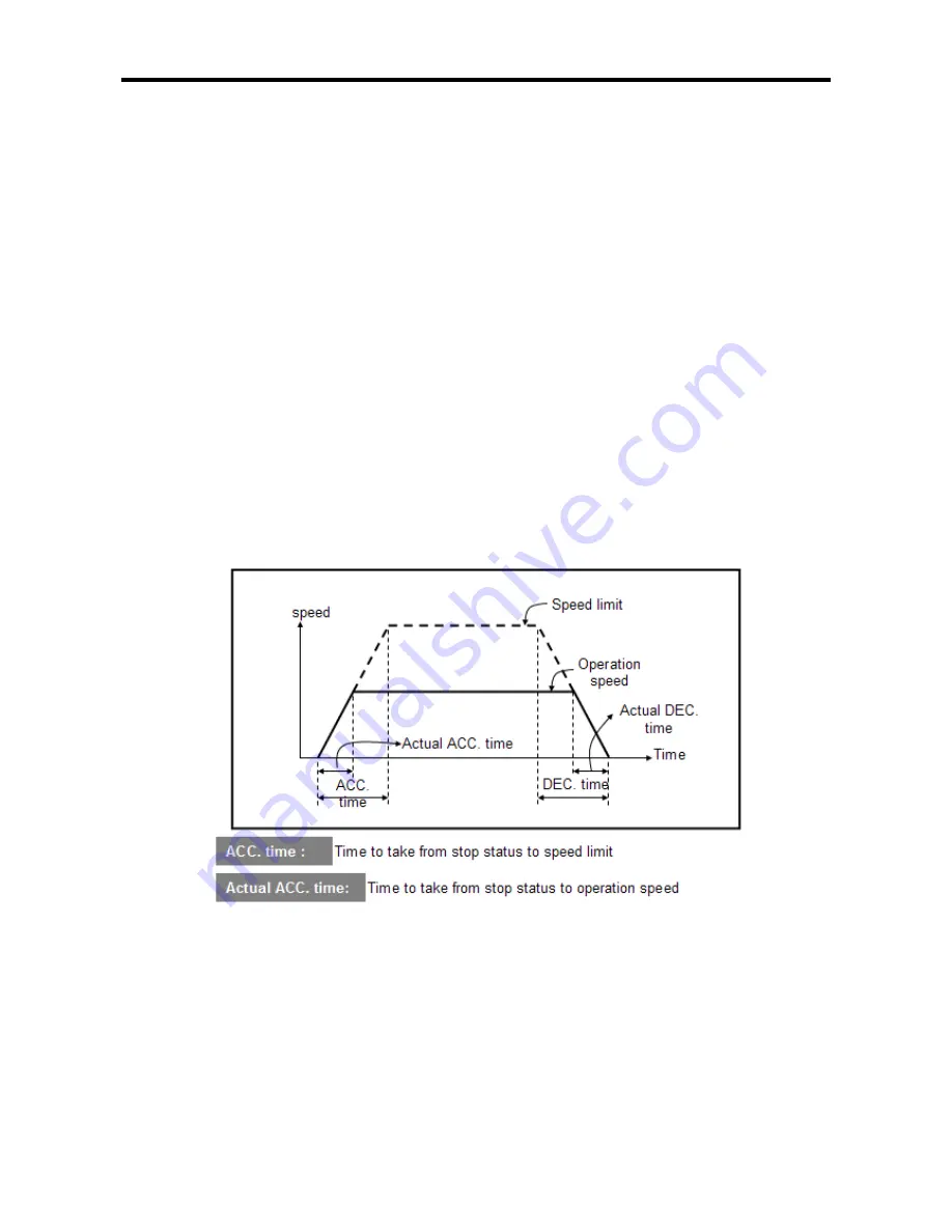
(7) ACC/DEC time
• It is applied to sequential operation instruction, speed override, positioning speed override during
positioning operation as well as start/end time of positioning operation. At this time, ACC and DEC
time is defined as shown below.
(a) ACC time: a duration required to reach from “0(stop)” speed to the speed limit set in parameter.
Using bias would be a time consumed to reach from bias speed set to the speed
limit set in parameter.
(b) DEC time: a duration required to reach from the speed limit set in parameter up to “0”(stop)
speed.
Using bias would be a time consumed to reach from bias speed set to the speed
limit set in parameter.
•
The range is between 0
∼
10,000 (unit: 1
㎳
) per axis.
•
ACC/DEC time is set with 4 types and it can be set differently according to each operation data.
(8) S/W Upper/Lower Limit
• A range of a machine’s move is called ‘stroke limit’, and it sets the upper/lower limits of stroke into
software upper limit and software lower limit and does not execute positioning if it operates out of
ranges set in the above.
Therefore, it is used to prevent against out-of-range of upper/lower limits resulting from incorrect
positioning address or malfunction by program error and it needs installing emergency stop limit
switch close to a machine’s stroke limit.
•Except S/W upper limit and lower limit, install limit switch for emergency stop near stroke limit of
machine.
Summary of Contents for XBC-DN20S
Page 210: ...Chapter 7 Program Examples of Positioning 7 6 2 XEC ...
Page 215: ...Chapter 7 Program Examples of Positioning 7 11 2 XEC ...
Page 220: ...Chapter 7 Program Examples of Positioning 7 16 2 XEC ...
Page 225: ...Chapter 7 Program Examples of Positioning 7 21 2 XEC ...
Page 232: ...Chapter 7 Program Examples of Positioning 7 28 2 XEC ...
Page 237: ...Chapter 7 Program Examples of Positioning 7 33 2 XEC ...
Page 240: ...Chapter 7 Program Examples of Positioning 7 36 ...
Page 309: ...Appendix 4 Dimension App 4 4 XBC DN64H XEC DN64H XEC DP64H XBC DR64H XEC DR64H ...
Page 311: ...Appendix 4 Dimension App 4 6 XBE DC08A XBE DC16A XBE TN08A XBE TN16A XBE DR16A XBE RY08A ...
Page 312: ...Appendix 4 Dimension App 4 7 5 Communication module XBL C41 21A XBL EMTA ...
Page 313: ...Appendix 4 Dimension App 4 8 5 Special module XBF AD04A XBF DV04A ...