


Learning Advanced Features
286
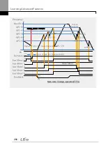
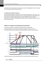
It is used to set a motor to the smallest number among Drives not inter-locked by [AP1-43 Starting
Aux] and place others in order based on it when operating time of every motor is deleted through
<1:All> of [AP1-98 AuxRunTime Clr].
In case that operating time of each motor is deleted through <2: Aux1> ~ <6: Aux5> of [AP1-98
AuxRunTime Clr] or changed by combining [AP1-96 AuxRunTime Day] and [AP1-97 AuxRunTime
Min], motor stopped changes the priority with motor stopped as operating motor does with
operating motor.
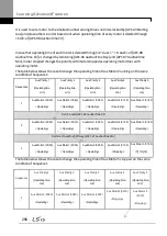
The table below shows the case to change the operating time of Aux Motor2 running on the same
condition of Sequence1.
Sequences
Aux Priority 1
(Operating time:
min)
Aux Priority 2
(Operating time:
min)
Aux Priority 3
(Operating time:
min)
Aux Priority 4
(Operating time:
min)
Aux Priority 5
(Operating time:
min)
1
Aux Motor3 (00:30)
<Operating>
Aux Motor2 (00:40)
<Operating>
Aux Motor1 (00:50)
<Operating>
Aux Motor4 (01:30)
<Operating>
Aux Motor 5 (01:50)
<Operating>
Set <3 Aux2of [AP1-98 AuxRunTime Clr]
2
Aux Motor2 (00:00)
<Operating>
Aux Motor3 (00:30)
<Operating>
Aux Motor1 (00:50)
<Operating>
Aux Motor4 (01:30)
<Operating>
Aux Motor 5 (01:50)
<Operating>
Set time of Aux2to 2:00 through [AP1-97 AuxRunTime Min]
3
Aux Motor3 (00:30)
<Operating>
Aux Motor1 (00:50)
<Operating>
Aux Motor2 (02:00)
<Operating>
Aux Motor4 (01:30)
<Stopping>
Aux Motor 5 (01:50)
<
정지상태
>
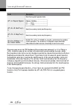
The table below shows the case to change the operating time of Aux Motor5
stopped
on the same
condition of Sequence1
Sequences
Aux Priority 1
(Operating time:
min)
Aux Priority 2
(Operating time:
min)
Aux Priority 3
(Operating time:
min)
Aux Priority 4
(Operating time:
min)
Aux Priority 5
(Operating time:
min)
1
Aux Motor3 (00:30)
<Operating>
Aux Motor2 (00:40)
<Operating>
Aux Motor1 (00:50)
<Operating>
Aux Motor4 (01:30)
<Stopping>
Aux Motor 5
(01:50)
<Stopping>
Summary of Contents for LSLV0055H100-4COFN
Page 14: ......
Page 18: ...Preparing the Installation 4 37 90 kW 3 Phase ...
Page 27: ...Preparing the Installation 13 ...
Page 47: ...33 Installing the Inverter ...
Page 48: ...Installing the Inverter 34 Input and Output Control Terminal Block Wiring Diagram ...
Page 61: ...47 Installing the Inverter ...
Page 71: ...Learning to Perform Basic Operations 57 ...
Page 88: ...Learning to Perform Basic Operations 74 ...
Page 103: ...89 Learning Basic Features Code Description V1 Quantizing ...
Page 129: ...115 Learning Basic Features ...
Page 140: ...Learning Basic Features 126 ...
Page 148: ...Learning Basic Features 134 ...
Page 171: ...157 Learning Advanced Features Deceleration dwell operation ...
Page 183: ...169 Learning Advanced Features ...
Page 184: ...Learning Advanced Features 170 PID Command Block ...
Page 185: ...171 Learning Advanced Features PID Feedback Block ...
Page 186: ...Learning Advanced Features 172 PID Output Block ...
Page 187: ...173 Learning Advanced Features PID Output Mode Block ...
Page 197: ...183 Learning Advanced Features ...
Page 201: ...187 Learning Advanced Features Code Description 100 EPID1 Control block ...
Page 202: ...Learning Advanced Features 188 EPID2 Control block ...
Page 237: ...223 Learning Advanced Features Time Period Schedule AP3 38 Except3 Day 01 01 ...
Page 244: ...Learning Advanced Features 230 ...
Page 259: ...245 Learning Advanced Features Code Description Code Description Volt ...
Page 362: ...Learning Protection Features 348 ...
Page 415: ...401 RS 485 Communication Features Item Standards Parity check None ...
Page 524: ...Table of Functions 510 ...
Page 533: ...Table of Functions 519 ...
Page 547: ...533 Troubleshooting ...
Page 585: ...Technical Specification 571 ...
Page 594: ...580 ...
Page 595: ...581 ...
Page 596: ...582 ...


