


219
Learning Advanced Features
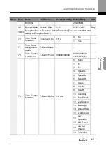
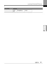
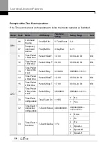
Code
Description
1 MM/DD/YYYY Month/Day/Year is displayed (USA).
2 DD/MM/YYYY The format of Day/Month/Year is displayed
(Europe).
AP3-10 Period Status
Bits 0–3 are used to indicate the time module that is currently in use
among the 4 different time modules set at AP3-11–AP3-22.
Bits 4–11 are used to indicate the exception day that is set at AP3-30–
AP3-53.
AP3-11–AP3-20
Period 1–4 Start T
The start time for the 4 time periods can be set up to 4.
AP3-12–AP3-21
Period 1–4 STop T
The end time for the 4 time periods can be set up to 4.
AP3-13–AP3-22
Period 1~4 Day
The Time period date for the operation can be set up to 4. It can be set
on a weekly basis. If the bit is ‗1 (on)‘, it indicates the relevant day is
selected. If the Bit is ‗0 (off)‘, it indicates the relevant day is not
selected.
Bit
6
5
4
3
2
1
0
Sunday
Monday Tuesday Wednesday Thursday Friday
Saturday
AP3-30–AP3-51
Exception1–8 Start T The operation start time for the 8 Exception days can be set.
AP3-31–AP3-52
Exception1–8 Stop T The operation end time for the 8 Exception days can be set.
AP3-32–AP3-53
Exception1–8 Date
The date for the 8 Exception days can be set.
AP3-70 Time Event
En
Enables or disables the Time Event
Setting
Function
0
No
Time Event is not used.
1
Yes
Time Event is used.
AP3-71 T-Event
Status
It shows which T-Event from 1–8 is being performed.
7
6
5
4
3
2
1
0
T-
Event
8
T-
Event
7
T-
Event
6
T-
Event
5
T-
Event
4
T-
Event
3
T-
Event
2
T-
Event
1
AP3-72–86 T-Event1–
8 Period
Select the desired module of the Time Module and Exception Day set
in AP3-11–AP3-53 for the relevant events.
If the bit is 1, it indicates the relevant Time Module or Exception Day is
selected. If the Bit is 0, it indicates the Time Module or Exception Day
Summary of Contents for LSLV0055H100-4COFN
Page 14: ......
Page 18: ...Preparing the Installation 4 37 90 kW 3 Phase ...
Page 27: ...Preparing the Installation 13 ...
Page 47: ...33 Installing the Inverter ...
Page 48: ...Installing the Inverter 34 Input and Output Control Terminal Block Wiring Diagram ...
Page 61: ...47 Installing the Inverter ...
Page 71: ...Learning to Perform Basic Operations 57 ...
Page 88: ...Learning to Perform Basic Operations 74 ...
Page 103: ...89 Learning Basic Features Code Description V1 Quantizing ...
Page 129: ...115 Learning Basic Features ...
Page 140: ...Learning Basic Features 126 ...
Page 148: ...Learning Basic Features 134 ...
Page 171: ...157 Learning Advanced Features Deceleration dwell operation ...
Page 183: ...169 Learning Advanced Features ...
Page 184: ...Learning Advanced Features 170 PID Command Block ...
Page 185: ...171 Learning Advanced Features PID Feedback Block ...
Page 186: ...Learning Advanced Features 172 PID Output Block ...
Page 187: ...173 Learning Advanced Features PID Output Mode Block ...
Page 197: ...183 Learning Advanced Features ...
Page 201: ...187 Learning Advanced Features Code Description 100 EPID1 Control block ...
Page 202: ...Learning Advanced Features 188 EPID2 Control block ...
Page 237: ...223 Learning Advanced Features Time Period Schedule AP3 38 Except3 Day 01 01 ...
Page 244: ...Learning Advanced Features 230 ...
Page 259: ...245 Learning Advanced Features Code Description Code Description Volt ...
Page 362: ...Learning Protection Features 348 ...
Page 415: ...401 RS 485 Communication Features Item Standards Parity check None ...
Page 524: ...Table of Functions 510 ...
Page 533: ...Table of Functions 519 ...
Page 547: ...533 Troubleshooting ...
Page 585: ...Technical Specification 571 ...
Page 594: ...580 ...
Page 595: ...581 ...
Page 596: ...582 ...


