
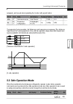


Learning Advanced Features
166
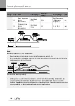
Code
Description
the value set at PID-13 PID Ref1AuxMod.
Setting
Function
0
None
Not used
1
V1
-10-10 V input voltage terminal
3
V2
I2 analog input terminal
[When the analog voltage/current input terminal
selection switch (SW4) at the terminal block is set
to I (current), input 0-20 mA current. If it is set to V
(voltage), input 0–10 V]
4
I2
6
Pulse
TI Pulse input terminal (0-32 kHz Pulse input)
7
Int. 485
RS-485 input terminal
8
FieldBus Communication command via a communication
option card
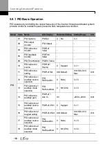
10 EPID1
Output
External PID 1 output
11
EPID1
Fdb Val
External PID 1 feedback
PID-22 PID FDB
AuxMod
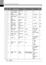
The PID-30 (PID FDB AuxMod) provides formulas to calculate the
final feedback value. If PID-31 (PID RefAuxSrc) is set to any other
value than ‗None,‘ the final feedback is calculated using the input
values at the sources (set at PID-31 and PID-32).
Setting
0
M+(G*A)
1
M*(G*A)
2
M/(G*A)
3
M+(M*(G*A))
4
M+G*2*(A-50)
5
M*(G*2*(A-50))
6
M/(G*2*(A-50))
7
M+M*G*2*(A-50)
8
(M-A)^2
9
M^2+A^2
10
MAX(M,A)
11
MIN(M,A)
12
(M+A)/2
13
Square Root(M+A)
M= Value by the source set at PID-30
G= Gain value set at PID-33
A= Value by the source set at PID-31
PID-23 PID Fdb Aux
G
Gain value used a formula set at PID-22.
Summary of Contents for LSLV0055H100-4COFN
Page 14: ......
Page 18: ...Preparing the Installation 4 37 90 kW 3 Phase ...
Page 27: ...Preparing the Installation 13 ...
Page 47: ...33 Installing the Inverter ...
Page 48: ...Installing the Inverter 34 Input and Output Control Terminal Block Wiring Diagram ...
Page 61: ...47 Installing the Inverter ...
Page 71: ...Learning to Perform Basic Operations 57 ...
Page 88: ...Learning to Perform Basic Operations 74 ...
Page 103: ...89 Learning Basic Features Code Description V1 Quantizing ...
Page 129: ...115 Learning Basic Features ...
Page 140: ...Learning Basic Features 126 ...
Page 148: ...Learning Basic Features 134 ...
Page 171: ...157 Learning Advanced Features Deceleration dwell operation ...
Page 183: ...169 Learning Advanced Features ...
Page 184: ...Learning Advanced Features 170 PID Command Block ...
Page 185: ...171 Learning Advanced Features PID Feedback Block ...
Page 186: ...Learning Advanced Features 172 PID Output Block ...
Page 187: ...173 Learning Advanced Features PID Output Mode Block ...
Page 197: ...183 Learning Advanced Features ...
Page 201: ...187 Learning Advanced Features Code Description 100 EPID1 Control block ...
Page 202: ...Learning Advanced Features 188 EPID2 Control block ...
Page 237: ...223 Learning Advanced Features Time Period Schedule AP3 38 Except3 Day 01 01 ...
Page 244: ...Learning Advanced Features 230 ...
Page 259: ...245 Learning Advanced Features Code Description Code Description Volt ...
Page 362: ...Learning Protection Features 348 ...
Page 415: ...401 RS 485 Communication Features Item Standards Parity check None ...
Page 524: ...Table of Functions 510 ...
Page 533: ...Table of Functions 519 ...
Page 547: ...533 Troubleshooting ...
Page 585: ...Technical Specification 571 ...
Page 594: ...580 ...
Page 595: ...581 ...
Page 596: ...582 ...


