


145
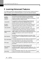
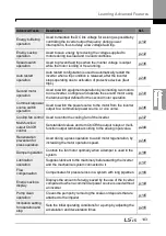
Learning Advanced Features
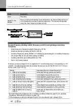
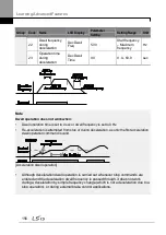
The table above lists the available calculated conditions for the main and auxiliary
frequency references. Refer to the table to see how the calculations apply to an example
where the DRV-06 Frq Src code has been set to ‗0 (Keypad-1)‘, and the inverter is
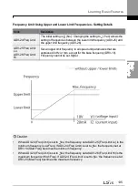
operating at a main reference frequency of 30.00 Hz. Signals at -10 to +10 V are received
at terminal V1, with the reference gain set at 5%. In this example, the resulting frequency
reference is fine-tuned within the range of 27.00–33.00 Hz [Codes IN-01–16 must be set to
the default values, and IN-06 (V1 Polarity), set to ‗1 (Bipolar)‘].
Auxiliary Reference Setting Details
Code
Description
BAS-01 Aux Ref
Src
Set the input type to be used for the auxiliary frequency reference.
Configuration Description
0 None
Auxiliary frequency reference is disabled
1 V1
Sets the V1 (voltage) terminal at the control terminal
block as the source of auxiliary frequency reference.
3 V2
Sets the I2 (voltage) terminal at the control terminal block
as the source of auxiliary frequency reference (SW4
must be set to ‗voltage‘).
4 I2
Sets the I2 (current) terminal at the control terminal block
as the source of auxiliary frequency reference (SW4
must be set to ‗current‘).
5 Pulse
Sets the TI (pulse) terminal at the control terminal block
as the source of auxiliary frequency reference.
BAS-02
Aux Calc Type
Set the auxiliary reference gain with BAS-03 (Aux Ref Gain) to configure
the auxiliary reference and set the percentage to be reflected when
calculating the main reference. Note that items 4–7 below may result in
either plus (+) or minus (-) references (forward or reverse operation) even
when unipolar analog inputs are used.
Configuration
Formula for frequency reference
0 M+(G*A)
Main ref(BAS-03x BAS-01xIN-01)
1 M*(G*A)
Main reference x(BAS-03x BAS-01)
2 M/(G*A)
Main reference /( BAS-03x BAS-01)
3 M+{M*(G*A)}
Main ref{ Main reference x(BAS-03x
BAS-01)}
4 M+G*2*(A-50) Main ref BAS-03x2x(BAS-01–50)xIN-
01
5 M*{G*2*(A-50)} Main reference x{ BAS-03x2x(BAS-01–50)}
6 M/{G*2*(A-50)} Main reference /{ BAS-03x2x(BAS-01–50)}
7 M+M*G*2*(A-
50)
Main ref Main reference x BAS-
03x2x(BAS-01–50)
M: Main frequency reference (Hz or rpm)
G: Auxiliary reference gain (%)
A: Auxiliary frequency reference (Hz or rpm) or gain (%)
BAS-03 Aux Ref Adjust the size of the input (BAS-01 Aux Ref Src) configured for auxiliary
Summary of Contents for LSLV0055H100-4COFN
Page 14: ......
Page 18: ...Preparing the Installation 4 37 90 kW 3 Phase ...
Page 27: ...Preparing the Installation 13 ...
Page 47: ...33 Installing the Inverter ...
Page 48: ...Installing the Inverter 34 Input and Output Control Terminal Block Wiring Diagram ...
Page 61: ...47 Installing the Inverter ...
Page 71: ...Learning to Perform Basic Operations 57 ...
Page 88: ...Learning to Perform Basic Operations 74 ...
Page 103: ...89 Learning Basic Features Code Description V1 Quantizing ...
Page 129: ...115 Learning Basic Features ...
Page 140: ...Learning Basic Features 126 ...
Page 148: ...Learning Basic Features 134 ...
Page 171: ...157 Learning Advanced Features Deceleration dwell operation ...
Page 183: ...169 Learning Advanced Features ...
Page 184: ...Learning Advanced Features 170 PID Command Block ...
Page 185: ...171 Learning Advanced Features PID Feedback Block ...
Page 186: ...Learning Advanced Features 172 PID Output Block ...
Page 187: ...173 Learning Advanced Features PID Output Mode Block ...
Page 197: ...183 Learning Advanced Features ...
Page 201: ...187 Learning Advanced Features Code Description 100 EPID1 Control block ...
Page 202: ...Learning Advanced Features 188 EPID2 Control block ...
Page 237: ...223 Learning Advanced Features Time Period Schedule AP3 38 Except3 Day 01 01 ...
Page 244: ...Learning Advanced Features 230 ...
Page 259: ...245 Learning Advanced Features Code Description Code Description Volt ...
Page 362: ...Learning Protection Features 348 ...
Page 415: ...401 RS 485 Communication Features Item Standards Parity check None ...
Page 524: ...Table of Functions 510 ...
Page 533: ...Table of Functions 519 ...
Page 547: ...533 Troubleshooting ...
Page 585: ...Technical Specification 571 ...
Page 594: ...580 ...
Page 595: ...581 ...
Page 596: ...582 ...


