


Learning Advanced Features
184
Note
•
The EPID1–2 output (EPID OUT) is bipolar, and is limited by the EPI-14 (EPID 1 Limit Hi)
and EPI-15 (EPID 1 Limit Lo) settings.
•
The following are the variables used in PID operation, and how they are calculated:
- Unit MAX = EPID1 (EPID2) Unit 100% (PID-68 )
- Unit Min = (2xEPID1 (EPID2) Unit0%-EPID1 (EPID2) Unit 100%)
- Unit Default = (EPID1 (EPID2) Unit 100%-EPID1 (EPID2) Unit 0%)/2
EPID Basic Operation Setting Details
Code
Description
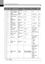
EPI-01 EPID1 Mode
Sets the EPID1 modes.
Setting
Function
0
None
EPID1 is not used.
1
Always On
EPID1 operates at all times.
2
During Run
Operates only when the inverter is running.
3
DI
Dependent
Operates when terminal input (EPID1 Run) is
on.
EPI-02 PID Output
Displays the existing output value for the EPID controller. The unit,
gain, and scale that were set in the EPID group are applied on the
display.
EPI-03 EPID Ref
Value
Displays the existing reference value set for the EPID controller. The
unit, gain, and scale that were set in the EPID group are applied on
the display.
EPI-04 EPID1 Fdb
Value
Displays the existing feedback value set for the EPID controller. The
unit, gain, and scale that were set in the EPID group are applied on
the display.
EPI-05 EPID1 Err
Value
Displays the difference between the existing reference and the
feedback (error value). The unit, gain, and scale that were set in the
PID group are applied on the display.
EPI1-06 EPID1 Ref
Src
Selects the reference input for the EPID control. If the V1 terminal is
set to an EPID1 feedback source (EPID1 F/B Source), V1 cannot be
set as the EPID1 reference source (EPID1 Ref Source). To set V1 as
a reference source, change the feedback source.
Setting
Function
0
Keypad
Keypad
1
V1
-10-10 V input voltage terminal
3
V2
I2 analog input terminal [When analog
voltage/current input terminal selection switch
4
I2
Summary of Contents for LSLV0055H100-4COFN
Page 14: ......
Page 18: ...Preparing the Installation 4 37 90 kW 3 Phase ...
Page 27: ...Preparing the Installation 13 ...
Page 47: ...33 Installing the Inverter ...
Page 48: ...Installing the Inverter 34 Input and Output Control Terminal Block Wiring Diagram ...
Page 61: ...47 Installing the Inverter ...
Page 71: ...Learning to Perform Basic Operations 57 ...
Page 88: ...Learning to Perform Basic Operations 74 ...
Page 103: ...89 Learning Basic Features Code Description V1 Quantizing ...
Page 129: ...115 Learning Basic Features ...
Page 140: ...Learning Basic Features 126 ...
Page 148: ...Learning Basic Features 134 ...
Page 171: ...157 Learning Advanced Features Deceleration dwell operation ...
Page 183: ...169 Learning Advanced Features ...
Page 184: ...Learning Advanced Features 170 PID Command Block ...
Page 185: ...171 Learning Advanced Features PID Feedback Block ...
Page 186: ...Learning Advanced Features 172 PID Output Block ...
Page 187: ...173 Learning Advanced Features PID Output Mode Block ...
Page 197: ...183 Learning Advanced Features ...
Page 201: ...187 Learning Advanced Features Code Description 100 EPID1 Control block ...
Page 202: ...Learning Advanced Features 188 EPID2 Control block ...
Page 237: ...223 Learning Advanced Features Time Period Schedule AP3 38 Except3 Day 01 01 ...
Page 244: ...Learning Advanced Features 230 ...
Page 259: ...245 Learning Advanced Features Code Description Code Description Volt ...
Page 362: ...Learning Protection Features 348 ...
Page 415: ...401 RS 485 Communication Features Item Standards Parity check None ...
Page 524: ...Table of Functions 510 ...
Page 533: ...Table of Functions 519 ...
Page 547: ...533 Troubleshooting ...
Page 585: ...Technical Specification 571 ...
Page 594: ...580 ...
Page 595: ...581 ...
Page 596: ...582 ...


