I472 GB I 01 19
31100284
27
G
B
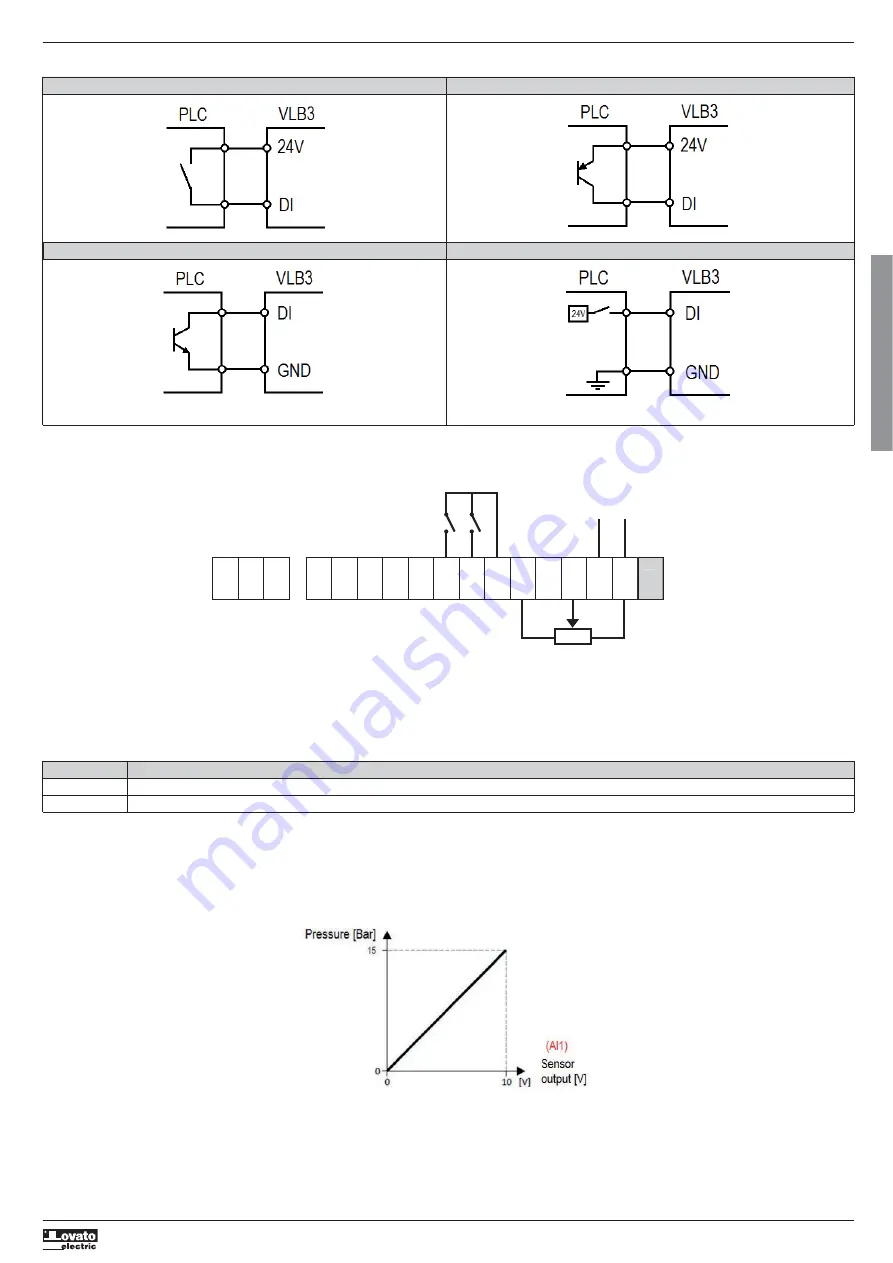
5.6.5 Command of digital inputs from PLC
Connection to PLC with dry contact output Connection to PLC with PNP output
Connection to PLC with NPN output Connection to PLC with tensioned output 24VDC
5.6.6 Configuration of the automatic (PID) / manual (frequency regulation) mode
The purpose of this configuration is to manage with a digital input the switching between two operating mode:
– Automatic mode (AUT): the variable speed drive works with an automatic PID control
– Manual mode (MAN): the variable speed drive is manually regulated in frequency .
In this example are used the following digital inputs:
Automatic mode (AUT)
In AUT mode the variable speed drive works with PID control, where the PID setpoint is set from keypad and the feedback is monitored from the AI1 analog input.
In this example we have assumed that on the AI1 analog input is connected a pressure sensor with output 0-10V, correspondent to a pressure of 0-15Bar with a linear characteristic, as shown in the following diagram.
This means that: if the output of the sensor is 0V it means a pressure of 0 Bar, if the output of the sensor is 10V it means a pressure of 15 Bar, if the output of the sensor is 5V it means a pressure of 7.5 Bar, and so on.
In addition, in this example we want to allow the user of the VLB3 to set a PID setpoint limited from 2 Bar to 8 Bar.
NO
COM
NC
24E
GND
AI1
AI2
AO1
10V
24V
DI1
DI2
DI3
DI4
DI5
DO1
GND
Run / Stop
24E
AUT / MAN mode
selection
Potentiometer
Sensor with
output 0...10VDC
+
–
Digital input Function
DI1 Command of the run/stop, independently from the selected mode (AUT/MAN).
DI2 Command the switching between the AUT and MAN mode: opened = AUT mode, closed = MAN mode.
Note. Set P410.01 = 0 (digital inputs assertion level = low)


