I472 GB I 01 19
31100284
G
B
16
3.6 CONNECTION OF THE SAFETY MODULE
3.6.1 Important notes
DANGER!
Improper installation of the safety engineering system can cause an uncontrolled starting action of the drives.
Possible consequences: death or severe injuries.
– Safety engineering systems may only be installed and commissioned by qualified and skilled personnel.
– All control components (switches, relays, PLC, ...) and the control cabinet must comply with the requirements of the EN ISO 13849-1 and the EN ISO 13849-2.
– Switches, relays with at least IP54 enclosure.
– Control cabinet with at least IP54 enclosure.
– It is essential to use insulated wire end ferrules for wiring.
– All safety relevant cables outside the control cabinet must be protected, e.g. by means of a cable duct.
– Ensure that no short circuits can occur according to the specifications of the EN ISO 13849-2.
– All further requirements and measures can be obtained from the EN ISO 13849−1 and the EN ISO 13849-2.
– If an external force acts upon the drive axes, additional brakes are required. Please observe that hanging loads are subject to the force of gravity!
– The user has to ensure that the drive will only be used in its intended application within the specified environmental conditions. This is the only way to comply with the declared safety-related
characteristics.
DANGER!
With the "Safe torque off" (STO) function, no "emergency stop" in terms
‑
EN 60204-1 can be executed without additional measures. There is no isolation between the motor and drive, no service
switch or maintenance switch!
Possible consequence: death or severe injuries.
– "Emergency stop" requires electrical isolation, e.g. by a central mains contactor.
DANGER!
Automatic restart if the request of the safety function is deactivated. Possible consequences: death or severe injuries.
– You must provide external measures according to EN ISO 13849−1 which ensure that the drive only restarts after a confirmation.
NOTICE!
Overvoltage.
Destruction of the safety component.
– The maximum voltage (maximum rated) at the safety inputs is 32 V DC. The user must make provisions to avoid that this voltage is exceeded.
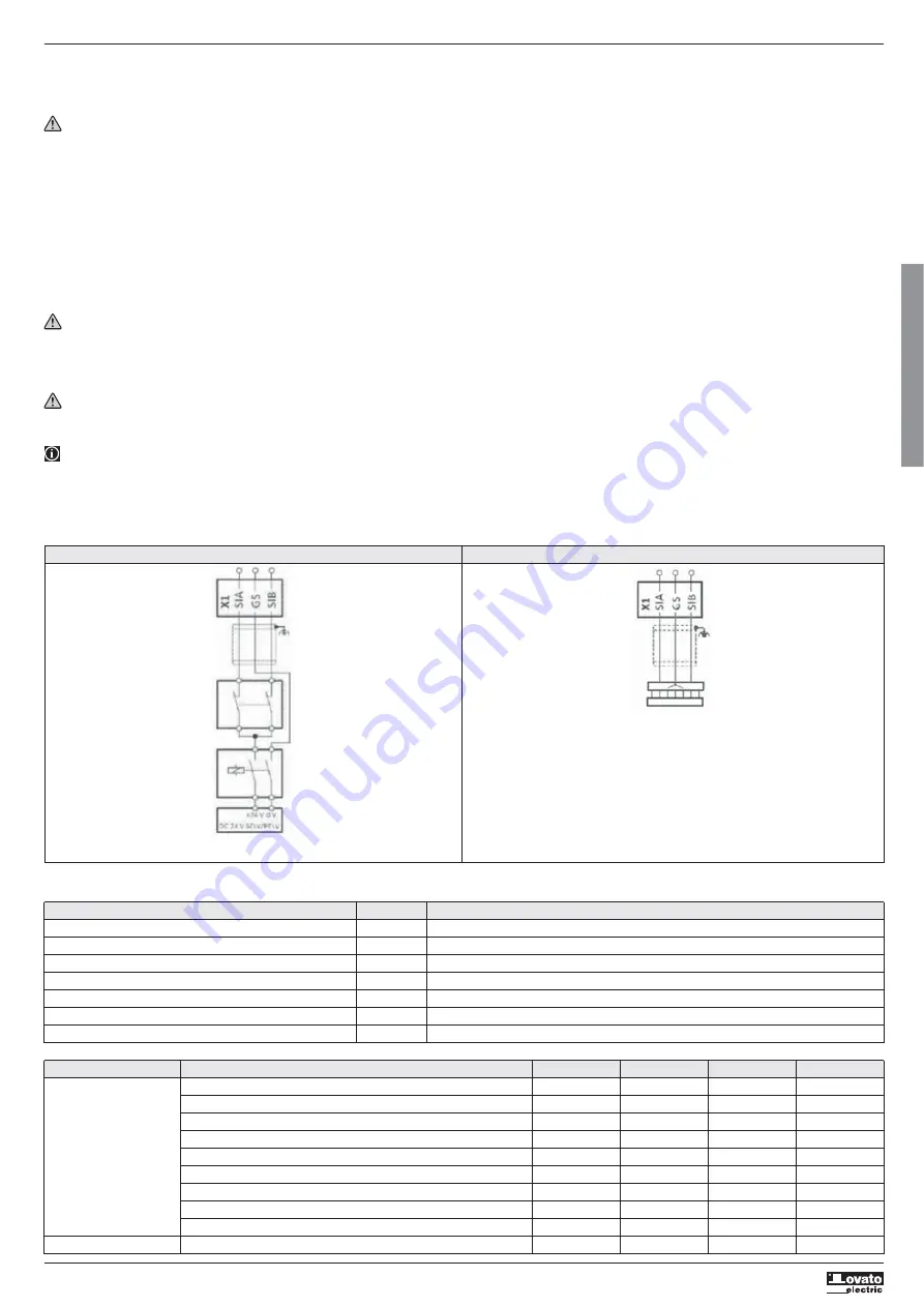
3.6.2 Connection plan
S1 safety switching device
S2 passive sensor
S1 active sensor - example lightgrid
Passive sensors Active sensors
3.6.3 Terminal Data
Terminal description Safety STO
Connection X1
Connection type Spring terminal
Min. cable cross-section mm
2
0.5
Max. cable cross-section mm
2
1.5
Stripping length mm 9
Tightening torque Nm 0.2
Required screwdriver 0.4x2.5
X1 Specification Unit min. typ. max.
SIA, SIB LOW signal V -3 0 +5
HIGH signal V +15 +24 +30
Running time ms 3
Input current SIA mA 10 14
Input current SIB mA 7 12
Input peak current mA 100
Tolerated test pulse ms 1
Switch-off time ms 50
Permissible distance of the test pulses ms 10
GS Reference potential for SIA and SIB
S1
S2
S1


