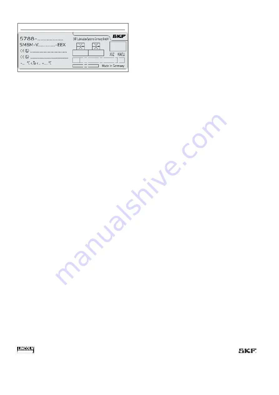
Lincoln SKF SMBM-V EEX Operating Instructions Manual Download Page 10


 10 


Fig. 2


Type plate of the SMBM-V 
 

1.11 Notes on CE marking 

CE marking is carried out in accordance with the requirements 
of the applied Directives requiring CE marking: 

  2014/30/EC Electromagnetic Compatibility 

  2011/65/EU Directive on the restriction of the use of certain 

hazardous substances in electrical and electronic equipment 
(RoHS II) 

  2014/34/EU Directive for equipment and protective systems 

intended for use in potentially explosive atmospheres (ATEX) 


1.12 Note on Low Voltage Directive 

The protection objectives of the Low Voltage Directive 
2014/35/EU are met in accordance with Annex II, No. 1.2.7 of 
the ATEX Directive 2014/34/EU. 
 

1.13 Note on Pressure Equipment 
Directive 

Due to its performance characteristics, the product does not 
reach the limit values defined in Article 4, Paragraph 1, 
Subparagraph (a) (ii) and is excluded from the scope of Pressure 
Equipment Directive 2014/68/EU in accordance with Article 1, 
Paragraph 2 Subparagraph (f). 
 

1.14 Emergency shutdown 

This is done by a course of action to be defined by the operator. 
 

1.15 Assembly, maintenance, fault, 
repair 

Prior to the start of this work, all relevant persons must be 
notified of it. At a minimum, the following safety measures must 
be taken before any work is done: 

  Unauthorized persons must be kept away 

  Mark and secure the work area 

  Cover adjacent live parts 

  Dry any wet, slippery surfaces or cover them appropriately 

  Cover hot or cold surfaces appropriately 

Where applicable: 

 Depressurize 

  Isolate, lock and tag out 

  Check to ensure live voltage is no longer present 

 Ground and short-circuit 

The product should be protected as much as possible from 

humidity, dust, and vibration, and should be installed so that it 
is easily accessible. Ensure an adequate distance from sources 
of heat or cold. Any visual monitoring devices present, such as 
pressure gauges, min./max. markings, or oil level gauges must 
be clearly visible. Observe the mounting position requirements. 

Drill required holes only on non-critical, non-load-bearing 

parts of the operator's infrastructure. Use existing holes where 
possible. Avoid chafe points. Immobilize any moving or detached 
parts during the work. Adhere to the specified torques. 

If guards or safety devices need to be removed, they must be 

reinstalled immediately following conclusion of work and then 
checked for proper function. 

Check new parts for compliance with the intended use before 

using them. 

Avoid mixing up or incorrectly assembling disassembled parts. 

Label parts. Clean any dirty parts. 
 

1.16 First start-up, daily start-up 

Ensure that: 

  All safety devices are fully present and functional 

  All connections are properly connected 

  All parts are correctly installed 

  All warning labels on the product are fully present, visible, and 

undamaged 

  Illegible or missing warning labels are immediately replaced 


1.17 Special safety instructions regarding 
explosion protection 

  Always behave so that explosion hazards are avoided.  

  A written work approval from the operator is required prior to 

working in potentially explosive areas. Keep unauthorized 
persons away. 

  There must be no indications that parts of the explosion 

protection are missing or are not working. Should such 
indications become apparent, switch off the machine and 
inform a superior without delay. 

  Measures for explosion protection must never be deactivated, 

modified or bypassed. 

  It is forbidden to bring in ignition sources such as sparks, 

open flames and hot surfaces in potentially explosive areas. 

  Check the machine at regular intervals for damage which may 

represent an ignition risk. 

  The ignition temperature of the lubricant must lie at least 

50 K over the maximum admissible surface temperature of 
the components. 

  Only use tools and clothing which are permitted for use in 

potentially explosive areas (ESD). 

  Transport, installation, repairs and work on electrical 

components may only be carried out, if it has been ensured 
that the atmosphere is not potentially explosive. 

  Repairs or modifications to machines which are protected 

against explosions may be carried out only by the 
manufacturer or by a workshop recognized by a named 
institution and confirmed in writing. If the work is not carried 
out by the manufacturer, the repairs must be approved by a 

Summary of Contents for SKF SMBM-V EEX

Page 1: ...Flow Limiters SMBM X and SMBM V EEX Created on 05 03 2021 Document no 951 180 090 EN Version 02 Read these instructions before installation or start up of the product and keep them readily available...

Page 2: ...with EN 60079 14 No 16 4 for use in potentially explosive atmospheres as defined in the ATEX Directive 2014 34 EU We hereby confirm that the signal transmitter Item number 24 1072 2125 Year of manufa...

Page 3: ...tion source results from the combination of the flow limiter described with the signal transmitters specified in these instructions as it is to be classified as simple electrical equipment in accordan...

Page 4: ...8 69190 Walldorf Germany Germany Tel 49 0 6227 33 0 Fax 49 0 6227 33 259 Warranty The instructions contain no statements regarding the warranty or liability for defects That information can be found...

Page 5: ...in nozzle table SMBM V with D1 and D2 20 3 4 Ordering a complete flow limiter assembly 21 3 5 Application 22 3 6 Functional description 22 3 7 Example of a circulating oil lubrication system with flow...

Page 6: ...unting with existing dummy module or replacement of an SMBM X module 58 9 4 2 New mounting with existing dummy module or replacement of an SMBM V module 59 9 4 3 Expansion of an existing flow limiter...

Page 7: ...ty or malfunctions Illustrations The illustrations used depict a specific product For other products they may have the function of a diagram only This does not alter the basic workings and operation o...

Page 8: ...erved Any unclear points regarding proper condition or correct assembly operation must be clarified Operation is prohibited until issues have been clarified Unauthorized persons must be kept away Wear...

Page 9: ...paint coat must meet the requirements of the standards applicable to ATEX Use in potentially explosive gases and vapors whose ignition temperature is less than 125 of the maximum surface temperature U...

Page 10: ...perator s infrastructure Use existing holes where possible Avoid chafe points Immobilize any moving or detached parts during the work Adhere to the specified torques If guards or safety devices need t...

Page 11: ...orized modifications Use of non original SKF spare parts components Non observance of these instructions and other applicable documents Use of non specified unsuitable operating materials Operation wi...

Page 12: ...instructions may have to be made accessible to other people and departments 1 24 4 Instruction and qualification obligations The operator clearly determines the responsibility of personnel for operati...

Page 13: ...avoided use flexible hose lines or anti kink coils and or conduits Lifecycles A Transport B Assembly C First start up D Operation E Cleaning F Maintenance G Malfunction repair H Shutdown K Disposal 1...

Page 14: ...m design The selection of a suitable lubricant should reasonably be made during the design of the machine and forms the basis for planning the centralized lubrication system The manufacturer operator...

Page 15: ...recommend performing this inspection after one week of machine downtime In case of doubt regarding the suitability of the lubricant replace it before putting into operation again and if necessary per...

Page 16: ...e flow indicator 333 pulses per liter without pulse generator max plug in nozzle size 295 02 with gear type flow indicator 167 pulses per liter without pulse generator 03 with gear type flow indicator...

Page 17: ...lug without cable Plug in nozzle index 3 digit code of the plug in nozzles for the SMBM X D1 see table 3 3 digit code of the plug in nozzles for the SMBM V D1 D2 see table 4 ATEX design EEX Further or...

Page 18: ...2 SMBM X22 code in the type identification code 22 3 SMBM X01 SMBM X02 oder SMBM X03 code in the type identification code 01 02 or 03 4 SMBM X11 SMBM X12 or SMBM X13 code in the type identification c...

Page 19: ...SMBM X D1 Table 3 Nominal volumetric flow2 Code1 l min pts min Item number Content 050 0 08 0 17 24 0455 2574 055 0 12 0 25 24 0455 2575 060 0 15 0 32 24 0455 2576 065 0 20 0 42 24 0455 2577 070 0 25...

Page 20: ...86 24 0455 2628 1 Coding in the type identification code 2 The nominal volumetric flows specified in the table are in reference to a dynamic viscosity of 300 mm2 s at an oil temperature of 20 C They...

Page 21: ...pe identification code 2 The nominal volumetric flows specified in the table are in reference to a dynamic viscosity of 300 mm2 s at an oil temperature of 20 C They are approximate values and may need...

Page 22: ...es The use of plug in nozzles makes it possible to set the oil quantity in increments from 0 08 to 8 l min 0 17 to 16 9 pts min One pump supplies the main pressure line with oil The flow limiters dire...

Page 23: ...low limiter p1 p1 2 p3 We recommend that a reserve of approximately 15 be provided for the selection of the oil pump Qpump 1 15 Qin Circulating oil lubrication systems with flow limiters which are equ...

Page 24: ...ontrol piston SK 5 Plug in nozzle D1 nonadjustable restrictor 6 Plug in nozzle D2 nonadjustable restrictor 7 Variable restrictor D3 8 Inner pressure p2 downstream of D1 D2 9 Spring force F 10 Stop scr...

Page 25: ...pump 1 now delivers the lubricant to the main pressure line 2 From here it travels through the oil filters 6 to the flow limiters 7 and then via downstream progressive metering devices 8 or flow divid...

Page 26: ...ow to a lower starting flow of 25 Once the target lubricant temperature has been reached on the return line to the reservoir the electrical 3 2 way changeover valve 9 is switched over to the plug in n...

Page 27: ...e generator 20 to 57 C With changeover device 20 to 57 C Lubricant temperature range 0 to 90 C at ambient temperature 60 C Measurement resolution proportional factor 333 pulses per liter 3 0 ml pulse...

Page 28: ...ing distance Sn 4 mm Effective sensing distance Sr 3 6 4 4 mm typ Secured sensing distance Sa 0 3 24 mm Switching frequency f 0 1500 Hz Nominal voltage U0 8 2 V Ri approx 1 k Hysteresis H 1 15 typ 5 T...

Page 29: ...eight 2 6 kg 4 5 Oil filter Table 16 Oil filter 24 0651 3041 Properties characteristics Value Content Type Metal grid filter Pumped medium temperature range 0 to 70 C Ambient temperature range 0 to 70...

Page 30: ...2624 305 7 31 15 45 24 0455 2625 310 7 48 15 81 24 0455 2626 315 7 72 16 32 24 0455 2627 320 7 98 16 86 24 0455 2628 1 Coding in the type identification code 2 The nominal volumetric flows specified i...

Page 31: ...455 2622 023 1 67 7 17 3 53 15 15 24 0455 2594 24 0455 2624 024 1 79 7 48 3 87 15 81 24 0455 2595 24 0455 2626 025 1 92 7 98 4 06 16 86 24 0455 2596 24 0455 2628 1 Coding in the type identification co...

Page 32: ...sure correction Legend 1 Nozzle index 2 Viscosity 150 mm2 s Differential pressure 50 150 bar 3 Viscosity 300 mm2 s Differential pressure 50 150 bar 4 Viscosity 600 mm2 s Differential pressure 50 150 b...

Page 33: ...05 and the working viscosity 300 mm2 s In this example it is 0 73 l min 1 54 pts min 2 Determination of the correction see diagram in Fig 13 Factor and calculation of the actual flow rate The correcti...

Page 34: ...served Required certificates must be included in the shipping documents The following information as a minimum must be marked on the packaging of return shipments Fig 14 Marking of return shipments 5...

Page 35: ...eginning installation It must be ensured that screw unions connections and connection elements are leak free Ensure cleanliness components must be installed without contamination Do not use any cleani...

Page 36: ...ting dimensions SMBM X00 Designation Dimension Content T Width 80 mm L Length 120 mm H Height 80 mm 6 3 2 SMBM X22 with signal transmitter Fig 16 Flow limiter with signal transmitter SMBM X22 Table 20...

Page 37: ...0 mm L Length 120 mm H Height 120 mm All further dimensions see drawing SMBM X00 6 3 4 SMBM X11 X12 X13 with gear type flow indicator and pulse generator Fig 18 Flow limiter with gear type flow indica...

Page 38: ...nting dimensions SMBM X51 X52 X53 Designation Dimension Content T Width 80 mm L Length 170 mm H Height 120 mm All further dimensions see drawing SMBM X00 6 3 6 Filter unit for SMBM X Fig 20 Filter uni...

Page 39: ...3 8 8 Filter unit with shut off valve Table 25 Attachment dimensions A B C D for SMBM X with maximum number of attached modules Dimensions mm 1 Module 2 Modules 3 Modules 4 Modules 5 Modules 6 Module...

Page 40: ...ght specifications refer to complete flow limiter assemblies without monitoring attachments and screw unions Weight specifications for monitoring units and attachments see Chapter 4 IMPORTANT NOTE Flo...

Page 41: ...ting dimensions SMBM V00 Designation Dimension Content T Width 80 mm L Length 150 mm H Height 80 mm 6 4 2 SMBM V22 with signal transmitter Fig 23 Flow limiter with signal transmitter SMBM V22 Table 28...

Page 42: ...nt T Width 80 mm L Length 150 mm H Height 120 mm All further dimensions see drawing SMBM V00 6 4 4 SMBM V11 V12 V13 with gear type flow indicator and pulse generator Fig 25 Flow limiter with gear type...

Page 43: ...nting dimensions SMBM V51 V52 V53 Designation Dimension Content T Width 80 mm L Length 170 mm H Height 120 mm All further dimensions see drawing SMBM V00 6 4 6 Filter unit for SMBM V Fig 27 Filter uni...

Page 44: ...for SMBM V Fig 28 Changeover valve for SMBM V Table 33 Minimum mounting dimensions changeover valve SMBM V Designation Dimension Content T Width 80 mm L Length 280 mm H Height 180 mm All further dimen...

Page 45: ...ig 29 Base plates for SMBM V Legend 1 Module 1 base module 2 Module 6 3 Expansion modules 2 to max 5 4 Connection module 5 Filter plate 6 Inlet G 1 2 7 Outlets G 3 8 8 Changeover valve 9 Filter unit w...

Page 46: ...ve 2 84 kg Weight of base plate for changeover valve with valve plate 1 61 kg Weight kg 1 Module 2 Modules 3 Modules 4 Modules 5 Modules 6 Modules Total weight of SMBM V with number of modules 2 82 4...

Page 47: ...and tighten them slightly 5 Align the flow limiter tighten the hexagon head screws with the following torque M8 15 1 Nm 6 Remove protective plugs at the inlet and the outlet if present 7 Attach the in...

Page 48: ...left can be implemented at the customer site with the SMBM X flow limiter except when a filter unit is attached This is not possible with the SMBM V flow limiter The plug screw 6 is to be tightened a...

Page 49: ...49 Fig 32 Mechanical connection options SMBM V...

Page 50: ...ious ignition protection ratings and the rules and regulations for devices and equipment in potentially explosive atmospheres The applicable national regulations and rules must be observed The signal...

Page 51: ...ightness NOTE Ensure that the ATEX connection cable provided by the customer is secured against strain and twisting Secure the ATEX connection cable accordingly if necessary 8 Attach the complete cabl...

Page 52: ...ten the cover fittings 2 4x Table 38 Spare parts accessories Designation Item number Content 3 2 changeover valve 24 1254 3437 II 2G Ex e mb IIC T4 Gb 6 10 Lubrication line connection CAUTION Risk of...

Page 53: ...over valve 24 1254 3437 is executed correctly Equipotential bonding fully present properly connected and electrically continuous The performance characteristics for the aforementioned connections matc...

Page 54: ...lied The lubricating oil must be free of air inclusions during its conveyance 8 1 Temporary shutdown Temporary shutdown is performed by disconnecting the hydraulic supply line 8 2 Permanent shutdown a...

Page 55: ...of the pulse generator 2340 00000091 is executed correctly If present electrical connection of the signal transmitter 24 1072 2113 is executed correctly If present electrical connection of the 3 2 cha...

Page 56: ...e the fitting mandrel to press the new plug in nozzle 4 and packing ring 4a into the bore of the control piston 3 without skewing Insert the pressure spring 5 into the control piston 3 Carefully inser...

Page 57: ...nozzle D1 Press new plug in nozzle D1 2 firmly into the control piston 5 all the way to the stop with the packing ring and the nozzle outlet pointing upward nozzle type legible Insert pressure spring...

Page 58: ...ging area of the base plate module with a suitable lint free cleaning cloth NOTE In the event that only one already mounted SMBM X module is to be replaced by a new SMBM X module proceed with the moun...

Page 59: ...hten the two screws evenly crosswise with a torque of 15 1 Nm 9 4 2 3 Replacement of an SMBM V module Place new packing rings 6a in the groove of boreholes 5 and 7 Carefully place the SMBM V module 10...

Page 60: ...WAF 6 in place and tighten it slightly as well Tighten the two screws evenly crosswise with a torque of 15 1 Nm 9 4 3 3 Initial installation of an SMBM V module Using the special tool for that purpose...

Page 61: ...61 Fig 40 Replacement of an SMBM module...

Page 62: ...62 Fig 41 Expansion of an existing assembly to include an SMBM module...

Page 63: ...for cleaning for materials see Chapter 2 Material compatibility NOTE Always completely remove any cleaning agent residue on the product and rinse with clear water This prevents the formation of alkali...

Page 64: ...of the cover then carefully screw it back in by hand up to the stop cover No monitoring signal Signal transmitter 24 1072 2125 Cable socket is not installed correctly Remount the cable socket and tig...

Page 65: ...ozzle Gear wheels are sticking ingress of foreign objects into the gear chamber Depressurize the system open the gear chamber clean the gear wheels and reinsert them observe arrangement and alignment...

Page 66: ...plosive atmospheres ESD The series 24 1072 2125 signal transmitter may be installed connected and commissioned only by technical personnel The technical personnel must have detailed knowledge of the v...

Page 67: ...can be removed accordingly using an open end wrench WAF 17 12 2 2 2 Mounting a new pulse generator Turn the two locknuts 6 7 already mounted on the new pulse generator 8 into the upper third of the th...

Page 68: ...ted with lubricant must be performed by a recognized waste disposal company in compliance with environmental protection requirements and waste disposal regulations as well as the requirements of local...

Page 69: ...fective parts identical in construction Modifications to existing products by the use of spare parts are therefore not permitted Fig 44 Structure of an SMBM X 14 1 Spare parts Table 48 SMBM X Module D...

Page 70: ...Content Copper sealing ring 1 DIN7603 A21X26 CU Copper sealing ring 1 DIN7603 A17X21 CU O Ring 12x2 6 WVN532 12x2 Table 52 Gasket kit for valve plate Item number 24 0404 2647 Comprised of Pcs Part num...

Page 71: ...20 2011 Throttle bushing SMBM V with O rings and retaining ring 1 24 0220 2022 Gearwheel with 1 bolt 1 24 1858 2218 Gearwheel with 2 bolts 1 24 1858 2219 Gearwheel with 4 bolts 1 24 1858 2220 Acrylic...

Page 72: ...straight with 5 m length Type V1 G N 5M PUR 1 24 1882 5005 Cable box angled with 15 m length TYPE V1 W N 15M PUR 1 24 1882 5016 Table 60 Fitting tool for check valve Item number 24 2104 2049 Designati...

Page 73: ...73...

Page 74: ...ered trademark of the SKF Group eLube is a trademark of the SKF Group SKF Group 2021 Reprint or reproduction of the contents of this information even in part is permitted only with SKF s prior written...

Reviews: