CAUTION—POTENTIAL INJURY:
To avoid the risk of fire or electrical shock, connect the power cord to
an appropriately rated and properly grounded electrical outlet that is near the product and easily
accessible.
CAUTION—POTENTIAL INJURY:
To avoid the risk of fire or electrical shock, use only the power cord
provided with this product or the manufacturer's authorized replacement.
CAUTION—POTENTIAL INJURY:
To reduce the risk of fire, use only a 26 AWG or larger
telecommunications (RJ-11) cord when connecting this product to the public switched telephone
network. For users in Australia, the cord must be approved by the Australian Communications and Media
Authority.
Warning—Potential Damage:
To avoid loss of data or printer malfunction, do not touch the USB cable, any
wireless network adapter, or the printer in the areas shown while actively printing.
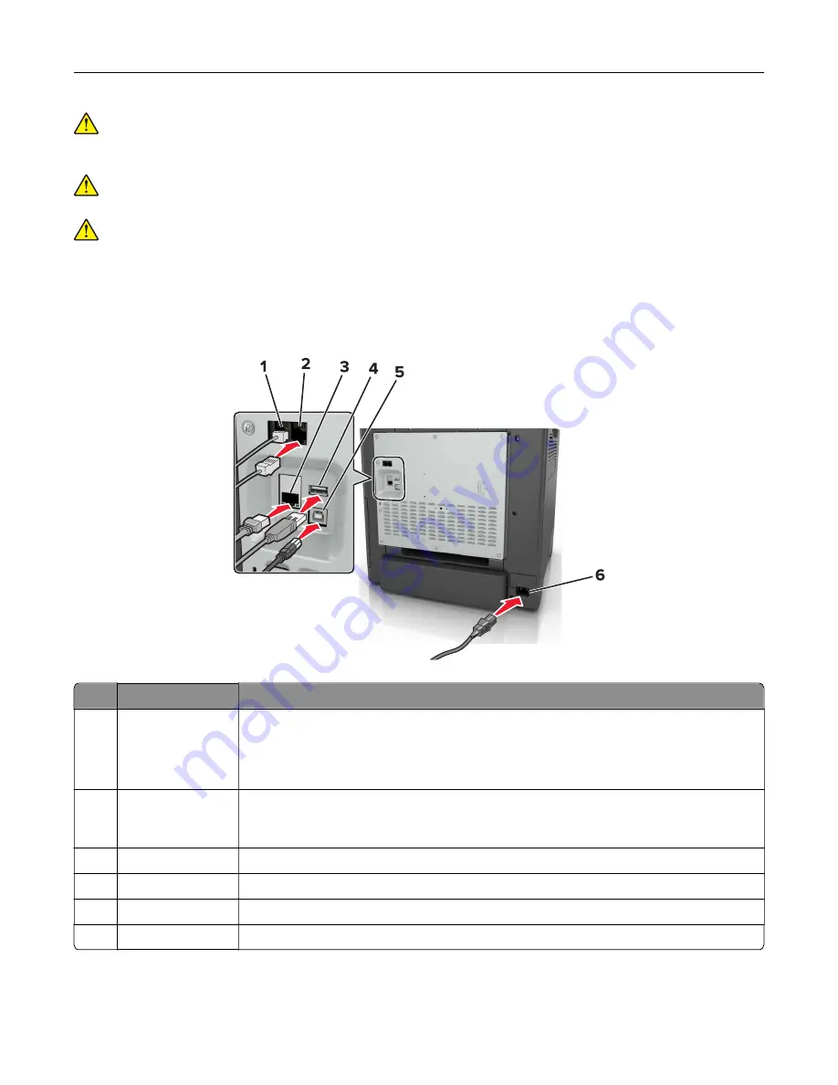
Use the
To
1
EXT port
Connect additional devices (telephone or answering machine) to the printer and the
telephone line. Use this port if you do not have a dedicated fax line for the printer and
if this connection method is supported in your country or region.
Note:
Remove the plug to access the port.
2
LINE port
Connect the printer to an active telephone line through a standard wall jack (RJ
‑
11), DSL
filter, or VoIP adapter, or any other adapter that allows you to access the telephone line
to send and receive faxes.
3
Ethernet port
Connect the printer to a network.
4
USB port
Attach a keyboard or any compatible option.
5
USB printer port
Connect the printer to a computer.
6
Power cord socket Connect the printer to a properly grounded electrical outlet.
Learning about the printer
14
Summary of Contents for XC4140
Page 60: ...5 Touch Scan Here If necessary change the scan settings 6 Scan the document Scanning 60 ...
Page 155: ...2 Remove the waste toner bottle 3 Remove the imaging kit Maintaining the printer 155 ...
Page 157: ...8 Insert the black toner cartridge 9 Insert the imaging kit Maintaining the printer 157 ...
Page 159: ...2 Remove the waste toner bottle 3 Remove the imaging kit Maintaining the printer 159 ...
Page 161: ...8 Insert the toner cartridges 9 Insert the new imaging kit Maintaining the printer 161 ...
Page 190: ...4 Close the duplex cover and door A Clearing jams 190 ...
Page 236: ...4 Insert the memory card until it clicks into place Upgrading and migrating 236 ...
Page 239: ...5 ISP extended cable 4 Install the ISP into its housing Upgrading and migrating 239 ...
Page 240: ...5 Attach the housing to the controller board access cover Upgrading and migrating 240 ...
Page 246: ...5 Open door B 6 Open door C Upgrading and migrating 246 ...


