


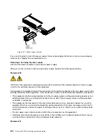

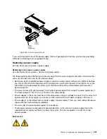


• Power supply 1 is the default/primary power supply. If power supply 1 fails, you must replace the power
supply with the same wattage immediately.
• You can order an optional power supply for redundancy.
• These power supplies are designed for parallel operation. In the event of a power-supply failure, the
redundant power supply continues to power the system. The server supports a maximum of two
power supplies.
Regulations
• It is the customer's responsibility to supply the necessary power cable.
To reduce the risk of electric
shock or energy hazards:
–
Use a circuit breaker that is rated at 25 amps.
–
Use 2.5 mm
2
(12 AWG) at 90°C copper wire.
–
Torque the wiring-terminal screws to 0.50 ~ 0.60 newton-meters (4.43 ~ 5.31 inch-pounds).
For more information, see “Statement 34” on page 257.
• If the power source requires ring terminals, you must use a crimping tool to install the ring terminals to
the power cord wires. The ring terminals must be UL approved and must accommodate the wire that is
described in the above-mentioned note .
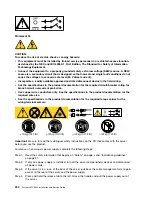
Statement 29
CAUTION:
This equipment is designed to permit the connection of the earthed conductor of the dc supply
circuit to the earthing conductor at the equipment.
This equipment is designed to permit the connection of the earthed conductor of the dc supply circuit to the
earthing conductor at the equipment. If this connection is made, all of the following conditions must be met:
• This equipment shall be connected directly to the dc supply system earthing electrode conductor or to a
bonding jumper from an earthing terminal bar or bus to which the dc supply system earthing electrode
conductor is connected.
• This equipment shall be located in the same immediate area (such as, adjacent cabinets) as any other
equipment that has a connection between the earthed conductor of the same dc supply circuit and the
earthing conductor, and also the point of earthing of the dc system. The dc system shall not be earthed
elsewhere.
• The dc supply source shall be located within the same premises as this equipment.
• Switching or disconnecting devices shall not be in the earthed circuit conductor between the dc source
and the point of connection of the earthing electrode conductor.
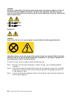
Statement 31
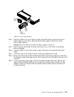
Removing and replacing components
255
Summary of Contents for x3550 M4
Page 1: ...System x3550 M4 Installation and Service Guide Machine Type 7914 ...
Page 6: ...iv System x3550 M4 Installation and Service Guide ...
Page 178: ...164 System x3550 M4 Installation and Service Guide ...
Page 322: ...308 System x3550 M4 Installation and Service Guide ...
Page 828: ...814 System x3550 M4 Installation and Service Guide ...
Page 986: ...972 System x3550 M4 Installation and Service Guide ...
Page 990: ...976 System x3550 M4 Installation and Service Guide ...
Page 1005: ......
Page 1006: ......


