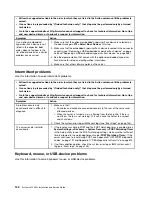

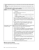
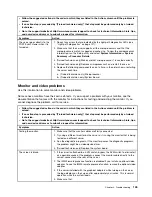

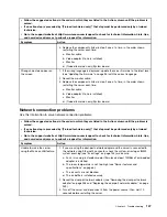

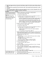

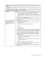
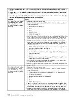
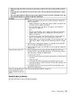


• Follow the suggested actions in the order in which they are listed in the Action column until the problem is
solved.
• If an action step is preceded by “(Trained technician only),” that step must be performed only by a trained
technician.
• Go to the support website at http://www.lenovo.com/support to check for technical information, hints, tips,
and new device drivers or to submit a request for information.
Symptom
Action
A USB device does not work.
1. Make sure that:
• The correct USB device driver is installed.
• The operating system supports USB devices.
2. Make sure that the USB configuration options are set correctly in the Setup
utility (see “Using the Setup utility” on page 97 for more information).
3. If you are using a USB hub, disconnect the USB device from the hub and
connect it directly to the server.
Video problems
Use this information to solve video problems.
See “Monitor and video problems” on page 145.
Solving power problems
Use this information to solve power problems.
Power problems can be difficult to solve. For example, a short circuit can exist anywhere on any of the
power distribution buses. Usually, a short circuit will cause the power subsystem to shut down because of
an overcurrent condition. To diagnose a power problem, use the following general procedure:
Step 1.
Turn off the server and disconnect all power cords.
Step 2.
Check for loose cables in the power subsystem. Also check for short circuits, for example, if a
loose screw is causing a short circuit on a circuit board.
Step 3.
Check the lit LEDs on the light path diagnostics panel (see “Light path diagnostics LEDs” on
page 124).
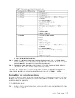
Step 4.
If the check log LED on the light path diagnostics panel is lit, check the IMM event log for faulty
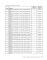
Pwr rail and complete the following steps. Table 17 “Components associated with power rail
errors” on page 157 identifies the components that are associated with each Pwr rail and the
order in which to troubleshoot the components.
a.
Disconnect the cables and power cords to all internal and external devices (see “Internal cable
routing and connectors” on page 179). Leave the power-supply cords connected.
b.
For Pwr rail 1 error, complete the following steps:
1. (Trained technician only) Replace the system board.
2. (Trained technician only) Replace the microprocessor.
c.
For other rail errors (Pwr rail 1 error, see Step b. on page 156), remove each component
that is associated with the faulty Pwr rail, one at a time, in the sequence indicated in Table
17 “Components associated with power rail errors” on page 157, restarting the server each
time, until the cause of the overcurrent condition is identified.
156
System x3550 M4 Installation and Service Guide
Summary of Contents for x3550 M4
Page 1: ...System x3550 M4 Installation and Service Guide Machine Type 7914 ...
Page 6: ...iv System x3550 M4 Installation and Service Guide ...
Page 178: ...164 System x3550 M4 Installation and Service Guide ...
Page 322: ...308 System x3550 M4 Installation and Service Guide ...
Page 828: ...814 System x3550 M4 Installation and Service Guide ...
Page 986: ...972 System x3550 M4 Installation and Service Guide ...
Page 990: ...976 System x3550 M4 Installation and Service Guide ...
Page 1005: ......
Page 1006: ......


