


00000000000000000000000000000000000
00000000000000000000000000000000000
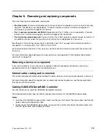
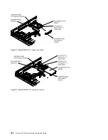
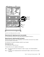
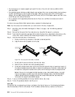
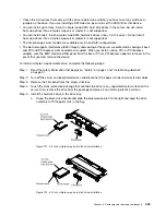
Figure 104. Operator information panel cable connection
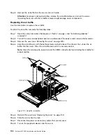
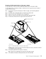
Cabling front USB and video connector
The internal routing and connectors for the front USB and video cables.
The following notes describe additional information you must consider when you install or remove the
front USB and video cables:
• To remove the front USB and video cables, slightly press the cables toward the chassis; then, pull to
remove the cables from the connectors on the system board. Pulling the cable out of the connector by
excessive force might cause damage to the cable or connector.
• To connect the front USB and video cables on the system board, press evenly on the cables. Pressing on
one side of the cable might cause damage to the cable or connector.
188
System x3550 M4 Installation and Service Guide
Summary of Contents for x3550 M4
Page 1: ...System x3550 M4 Installation and Service Guide Machine Type 7914 ...
Page 6: ...iv System x3550 M4 Installation and Service Guide ...
Page 178: ...164 System x3550 M4 Installation and Service Guide ...
Page 322: ...308 System x3550 M4 Installation and Service Guide ...
Page 828: ...814 System x3550 M4 Installation and Service Guide ...
Page 986: ...972 System x3550 M4 Installation and Service Guide ...
Page 990: ...976 System x3550 M4 Installation and Service Guide ...
Page 1005: ......
Page 1006: ......


