Front I/O assembly
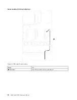
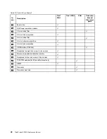
Use this section to understand the cable routing for the front I/O assembly.
Figure 15. Cable routing for the front I/O assembly
From
To
1
Front USB cable
Front USB connector on the system board
2
Operator-information-panel cable
Operator-information-panel connector on the system board
.
35
Summary of Contents for ThinkSystem SR530
Page 1: ...ThinkSystem SR530 Maintenance Manual Machine Types 7X07 and 7X08 ...
Page 8: ...vi ThinkSystem SR530 Maintenance Manual ...
Page 24: ...16 ThinkSystem SR530 Maintenance Manual ...
Page 52: ...44 ThinkSystem SR530 Maintenance Manual ...
Page 72: ...64 ThinkSystem SR530 Maintenance Manual ...
Page 74: ...66 ThinkSystem SR530 Maintenance Manual ...
Page 170: ...162 ThinkSystem SR530 Maintenance Manual ...
Page 174: ...166 ThinkSystem SR530 Maintenance Manual ...
Page 178: ...170 ThinkSystem SR530 Maintenance Manual ...
Page 183: ......
Page 184: ......


